
ProLiant DL740 Server Maintenance and Service Guide


Table Of Contents
- HP ProLiant DL740 Server Maintenance and Service Guide
- Notice
- Contents
- About This Guide
- Chapter 1: Illustrated Parts Catalog
- Chapter 2: Service Preparation
- Chapter 3: Chassis Components Removal and Replacement Procedures
- Chapter 4: Host Module Removal and Replacement Procedures
- Chapter 5: Power and Media Module Removal and Replacement Procedures
- Chapter 6: Diagnostic Tools
- Chapter 7: Connectors, Switches, and LED Indicators
- Connectors
- System Board
- Switches
- LED Indicators
- System Power LED Switch
- Unit Identification LED Switches (Front and Rear)
- System Interconnect LED Indicators
- System Attention LED Indicators
- System Activity LED Indicators
- Hot-Plug SCSI Hard Drive LED Indicators
- Power Supply LED Indicators
- Hot-Plug Fan LED Indicators
- PCI Hot Plug LED Indicators
- Memory Cartridge LED Indicators
- DIMM Status LED Indicators
- Chapter 8: Physical, Operating, and Performance Specifications
- Index
Host Module Removal and Replacement Procedures
HP ProLiant DL740 Server Maintenance and Service Guide 4-17
HP CONFIDENTIAL Codename: Jethro Part Number: 270853-004 Last Saved On: 2/13/04 10:40 AM
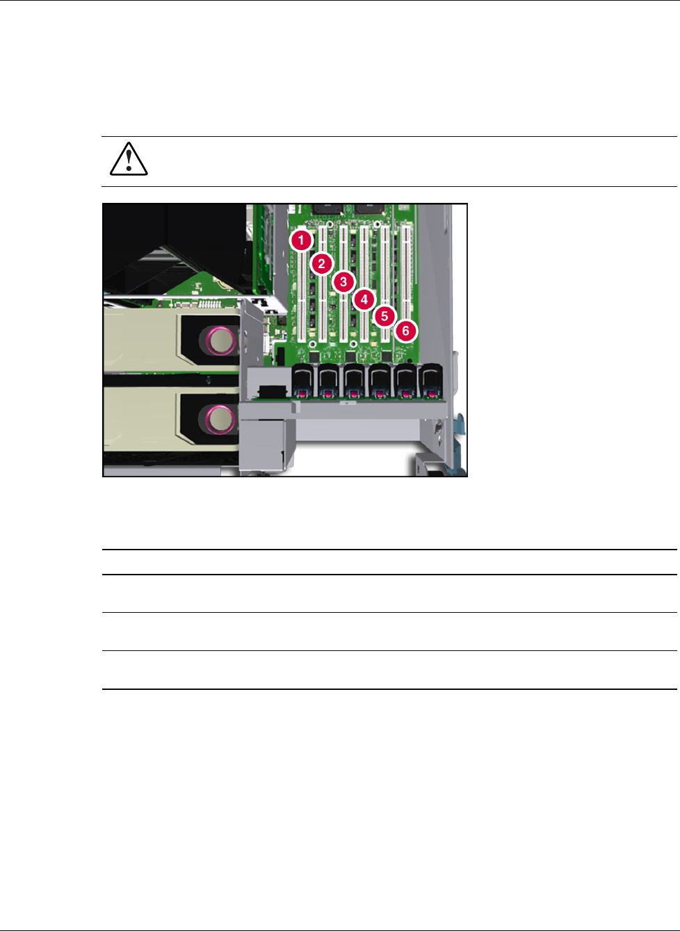
Locating the I/O Expansion Slots
The I/O expansion slots are located in the host module and are accessed by sliding the server
out of the rack and opening the top access panels, as described in Chapter 3. The I/O
expansion slots are distributed among three separate PCI-X buses.
WARNING: To reduce the risk of personal injury from hot surfaces, allow the internal
system components to cool before touching them.
Figure 4-15: Top view of I/O slots
Table 4-2: I/O Expansion Slots
Slot Description
Slots 1 and 2 PCI bus 7—Supports 64-bit PCI-X ex pansion boards at 100 MHz; it is keyed for
3.3 V signaling.
Slots 3 and 4 PCI bus 11—Supports 64-bit PCI-X ex pansion boards at 100 MHz; it is keyed for
3.3 V signaling.
Slots 5 and 6 PCI bus 3—Supports 64-bit PCI-X ex pansion boards at 100 MHz; it is keyed for
3.3 V signaling.
NOTE: Each PCI-X bus automatically configures to run in the most advanced mode (PCI-X or PCI)
and the highest frequency supported by all expansion boards installed in the slots on the bus.
PCI Hot Plug Button
The PCI Hot Plug button provides PCI Hot Plug hardware control without requiring you to
first run the PCI Hot Plug Utility software. Press the port-colored PCI Hot Plug button once
to power down or power up a slot. You can cancel an action by pressing the button again
within five seconds. When you press the button, the system automatically stops or starts
expansion board drivers. Refer to Figure 4-16, Figure 4-17, and Table 4-3 to locate the PCI
Hot Plug button.