
ProLiant DL740 Server Maintenance and Service Guide

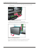
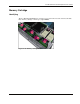


Table Of Contents
- HP ProLiant DL740 Server Maintenance and Service Guide
- Notice
- Contents
- About This Guide
- Chapter 1: Illustrated Parts Catalog
- Chapter 2: Service Preparation
- Chapter 3: Chassis Components Removal and Replacement Procedures
- Chapter 4: Host Module Removal and Replacement Procedures
- Chapter 5: Power and Media Module Removal and Replacement Procedures
- Chapter 6: Diagnostic Tools
- Chapter 7: Connectors, Switches, and LED Indicators
- Connectors
- System Board
- Switches
- LED Indicators
- System Power LED Switch
- Unit Identification LED Switches (Front and Rear)
- System Interconnect LED Indicators
- System Attention LED Indicators
- System Activity LED Indicators
- Hot-Plug SCSI Hard Drive LED Indicators
- Power Supply LED Indicators
- Hot-Plug Fan LED Indicators
- PCI Hot Plug LED Indicators
- Memory Cartridge LED Indicators
- DIMM Status LED Indicators
- Chapter 8: Physical, Operating, and Performance Specifications
- Index
Host Module Removal and Replacement Procedures
4-12 HP ProLiant DL740 Server Maintenance and Service Guide
HP CONFIDENTIAL Codename: Jethro Part Number: 270853-004 Last Saved On: 2/13/04 10:40 AM
DIMM Overview
The ProLiant DL740 server has five memory cartridges, each consisting of eight DIMMs.
The server supports up to 32 GB of usable memory with 8 GB of redundant memory.
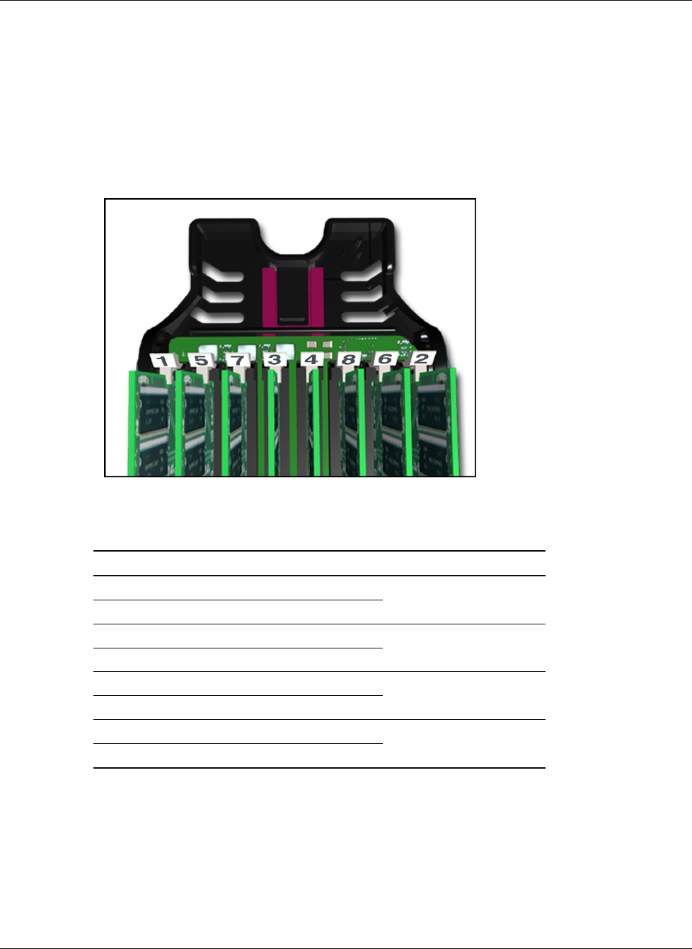
Locating the DIMM Sockets
Figure 4-13 and Table 4-1 detail the DIMM socket locations on the memory cartridge.
Figure 4-13: DIMM socket location
Table 4-1: DIMM Socket Location
Item Description Bank
1 DIMM socket 1 DIMM bank 1
2 DIMM socket 2 DIMM bank 2
Bank pair for interleaving
3 DIMM socket 3 DIMM bank 3
4 DIMM socket 4 DIMM bank 4
Bank pair for interleaving
5 DIMM socket 5 DIMM bank 5
6 DIMM socket 6 DIMM bank 6
Bank pair for interleaving
7 DIMM socket 7 DIMM bank 7
8 DIMM socket 8 DIMM bank 8
Bank pair for interleaving