
ProLiant DL740 Server Maintenance and Service Guide

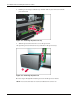
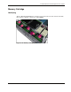


Table Of Contents
- HP ProLiant DL740 Server Maintenance and Service Guide
- Notice
- Contents
- About This Guide
- Chapter 1: Illustrated Parts Catalog
- Chapter 2: Service Preparation
- Chapter 3: Chassis Components Removal and Replacement Procedures
- Chapter 4: Host Module Removal and Replacement Procedures
- Chapter 5: Power and Media Module Removal and Replacement Procedures
- Chapter 6: Diagnostic Tools
- Chapter 7: Connectors, Switches, and LED Indicators
- Connectors
- System Board
- Switches
- LED Indicators
- System Power LED Switch
- Unit Identification LED Switches (Front and Rear)
- System Interconnect LED Indicators
- System Attention LED Indicators
- System Activity LED Indicators
- Hot-Plug SCSI Hard Drive LED Indicators
- Power Supply LED Indicators
- Hot-Plug Fan LED Indicators
- PCI Hot Plug LED Indicators
- Memory Cartridge LED Indicators
- DIMM Status LED Indicators
- Chapter 8: Physical, Operating, and Performance Specifications
- Index

Host Module Removal and Replacement Procedures
HP ProLiant DL740 Server Maintenance and Service Guide 4-7
HP CONFIDENTIAL Codename: Jethro Part Number: 270853-004 Last Saved On: 2/13/04 10:40 AM
4. Push the lever latch forward to release the processor board lever (1).
5. Lift the processor board lever up (2) and lift the processor board out of the module (3).
Figure 4-6: Removing the processor board
6. Push in the four tabs on the side of the processor board cover (1) and then lift the cover
off the processor board (2).
Figure 4-7: Removing the processor board cover
7. Turn over the processor board to access the processor clips.