
ProLiant DL740 Server Maintenance and Service Guide


Table Of Contents
- HP ProLiant DL740 Server Maintenance and Service Guide
- Notice
- Contents
- About This Guide
- Chapter 1: Illustrated Parts Catalog
- Chapter 2: Service Preparation
- Chapter 3: Chassis Components Removal and Replacement Procedures
- Chapter 4: Host Module Removal and Replacement Procedures
- Chapter 5: Power and Media Module Removal and Replacement Procedures
- Chapter 6: Diagnostic Tools
- Chapter 7: Connectors, Switches, and LED Indicators
- Connectors
- System Board
- Switches
- LED Indicators
- System Power LED Switch
- Unit Identification LED Switches (Front and Rear)
- System Interconnect LED Indicators
- System Attention LED Indicators
- System Activity LED Indicators
- Hot-Plug SCSI Hard Drive LED Indicators
- Power Supply LED Indicators
- Hot-Plug Fan LED Indicators
- PCI Hot Plug LED Indicators
- Memory Cartridge LED Indicators
- DIMM Status LED Indicators
- Chapter 8: Physical, Operating, and Performance Specifications
- Index
Host Module Removal and Replacement Procedures
4-6 HP ProLiant DL740 Server Maintenance and Service Guide
HP CONFIDENTIAL Codename: Jethro Part Number: 270853-004 Last Saved On: 2/13/04 10:40 AM
Removing Processor Boards and Processors
WARNING: The host module weighs more than 15.88 kg (35 lbs). HP recommends
either removing ALL of the memory cartridges before handling the module or having
two people handle the module together.
To remove the processor boards and processors:
1. Power down the server. Refer to “Powering Down the Server” in Chapter 2.
WARNING: To reduce the risk of personal injury from hot surfaces, allow the internal
system components to cool before touching them.
2. Remove the host module. Refer to “Removing the Host Module” in this chapter.
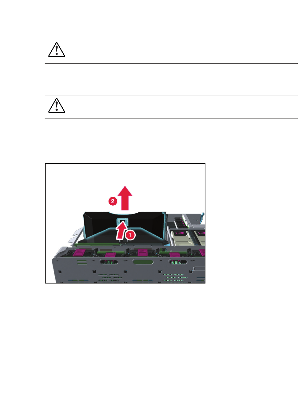
3. If a processor board air baffle is installed (in the case of a single processor board
configuration), remove it before removing the processor board. Remove the processor
board air baffle by pressing in the release tab (1) while pulling the air baffle up (2).
Figure 4-5: Removing the processor board air baffle