
ProLiant DL740 Server Maintenance and Service Guide

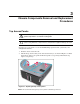


Table Of Contents
- HP ProLiant DL740 Server Maintenance and Service Guide
- Notice
- Contents
- About This Guide
- Chapter 1: Illustrated Parts Catalog
- Chapter 2: Service Preparation
- Chapter 3: Chassis Components Removal and Replacement Procedures
- Chapter 4: Host Module Removal and Replacement Procedures
- Chapter 5: Power and Media Module Removal and Replacement Procedures
- Chapter 6: Diagnostic Tools
- Chapter 7: Connectors, Switches, and LED Indicators
- Connectors
- System Board
- Switches
- LED Indicators
- System Power LED Switch
- Unit Identification LED Switches (Front and Rear)
- System Interconnect LED Indicators
- System Attention LED Indicators
- System Activity LED Indicators
- Hot-Plug SCSI Hard Drive LED Indicators
- Power Supply LED Indicators
- Hot-Plug Fan LED Indicators
- PCI Hot Plug LED Indicators
- Memory Cartridge LED Indicators
- DIMM Status LED Indicators
- Chapter 8: Physical, Operating, and Performance Specifications
- Index
Host Module Removal and Replacement Procedures
HP ProLiant DL740 Server Maintenance and Service Guide 4-5
HP CONFIDENTIAL Codename: Jethro Part Number: 270853-004 Last Saved On: 2/13/04 10:40 AM
The ProLiant DL740 server supports four or eight Intel Xeon processors MP.
• All processors must be the same speed, cache size, and stepping.
NOTE: Stepping refers to the processor revision.
• Processor board slot 1 must always be populated with a processor board to properly
terminate the processor bus.
NOTE: If the server has one processor board (four processors), processor board slot 2 is populated
with a processor board air baffle. This baffle must be removed to install the second processor board.
Refer to the instructions included with the processor board option for more information.
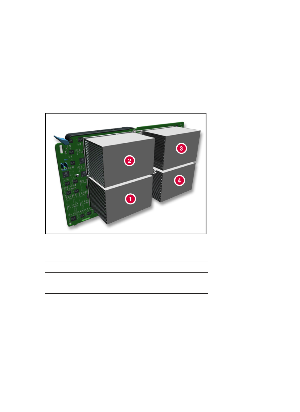
Figure 4-4: Processors
Item Description
1 Intel Xeon processor MP in socket 1
2 Intel Xeon processor MP in socket 2
3 Intel Xeon processor MP in socket 3
4 Intel Xeon processor MP in socket 4