
ProLiant DL740 Server Maintenance and Service Guide

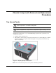


Table Of Contents
- HP ProLiant DL740 Server Maintenance and Service Guide
- Notice
- Contents
- About This Guide
- Chapter 1: Illustrated Parts Catalog
- Chapter 2: Service Preparation
- Chapter 3: Chassis Components Removal and Replacement Procedures
- Chapter 4: Host Module Removal and Replacement Procedures
- Chapter 5: Power and Media Module Removal and Replacement Procedures
- Chapter 6: Diagnostic Tools
- Chapter 7: Connectors, Switches, and LED Indicators
- Connectors
- System Board
- Switches
- LED Indicators
- System Power LED Switch
- Unit Identification LED Switches (Front and Rear)
- System Interconnect LED Indicators
- System Attention LED Indicators
- System Activity LED Indicators
- Hot-Plug SCSI Hard Drive LED Indicators
- Power Supply LED Indicators
- Hot-Plug Fan LED Indicators
- PCI Hot Plug LED Indicators
- Memory Cartridge LED Indicators
- DIMM Status LED Indicators
- Chapter 8: Physical, Operating, and Performance Specifications
- Index
Host Module Removal and Replacement Procedures
HP ProLiant DL740 Server Maintenance and Service Guide 4-3
HP CONFIDENTIAL Codename: Jethro Part Number: 270853-004 Last Saved On: 2/13/04 10:40 AM
8. Set the host module aside for servicing non-hot-plug components.
WARNING: To reduce the risk of personal injury from hot surfaces, allow the internal
system components to cool before touching them.
NOTE: Top panel labels provide instructions about installing expansion boards, setting switches, and
installing hot-plug fans, along with information about PCI Hot Plug. Refer to Chapter 5 for hot-plug
procedures.
To reassemble the server:
1. Slide the module in until the cam levers begin to rotate. Then push the cam levers shut
until they snap into place.
2. Reinstall the processor boards.
3. Reinstall the cable management system harness and I/O cables in the reverse order from
the steps used to remove them.