
ProLiant DL740 Server Maintenance and Service Guide


Table Of Contents
- HP ProLiant DL740 Server Maintenance and Service Guide
- Notice
- Contents
- About This Guide
- Chapter 1: Illustrated Parts Catalog
- Chapter 2: Service Preparation
- Chapter 3: Chassis Components Removal and Replacement Procedures
- Chapter 4: Host Module Removal and Replacement Procedures
- Chapter 5: Power and Media Module Removal and Replacement Procedures
- Chapter 6: Diagnostic Tools
- Chapter 7: Connectors, Switches, and LED Indicators
- Connectors
- System Board
- Switches
- LED Indicators
- System Power LED Switch
- Unit Identification LED Switches (Front and Rear)
- System Interconnect LED Indicators
- System Attention LED Indicators
- System Activity LED Indicators
- Hot-Plug SCSI Hard Drive LED Indicators
- Power Supply LED Indicators
- Hot-Plug Fan LED Indicators
- PCI Hot Plug LED Indicators
- Memory Cartridge LED Indicators
- DIMM Status LED Indicators
- Chapter 8: Physical, Operating, and Performance Specifications
- Index
3
Chassis Components Removal and Replacement
Procedures
Top Access Panels
WARNING: To reduce the risk of personal injury from hot surfaces, allow the internal
system components to cool before touching them.
CAUTION: When the server is powered on, the access panels must be installed for proper
system cooling. Otherwise, component stress and permanent equipment damage can result.
Open the top access panels to access the PCI Hot Plug expansion slots, system fans, and
configuration switches.
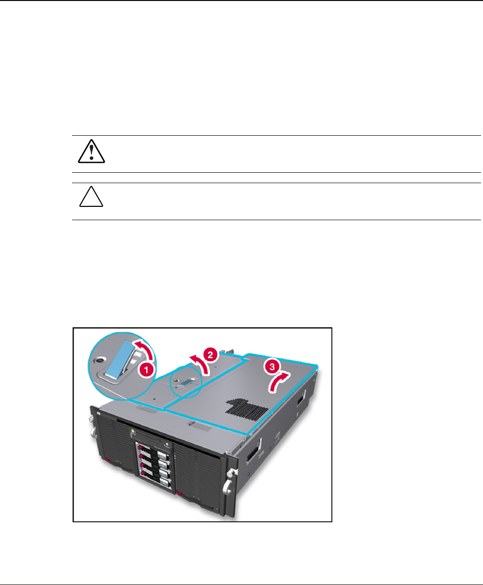
1. Slide the chassis out of the rack.
2. Unlock the top latch security screw and raise the latch (1), as shown in Figure 3-1. Hold
down the top right access panel and lift the top left access panel (2). Then lift the top
right access panel (3).
Figure 3-1: Opening the top access panels
NOTE: HP recommends leaving the top access panels locked during normal use.
HP ProLiant DL740 Server Maintenance and Service Guide 3-1
HP CONFIDENTIAL Codename: Jethro Part Number 270853-004 Last Saved On: 2/10/04 3:47 PM