
ProLiant DL740 Server Maintenance and Service Guide


Table Of Contents
- HP ProLiant DL740 Server Maintenance and Service Guide
- Notice
- Contents
- About This Guide
- Chapter 1: Illustrated Parts Catalog
- Chapter 2: Service Preparation
- Chapter 3: Chassis Components Removal and Replacement Procedures
- Chapter 4: Host Module Removal and Replacement Procedures
- Chapter 5: Power and Media Module Removal and Replacement Procedures
- Chapter 6: Diagnostic Tools
- Chapter 7: Connectors, Switches, and LED Indicators
- Connectors
- System Board
- Switches
- LED Indicators
- System Power LED Switch
- Unit Identification LED Switches (Front and Rear)
- System Interconnect LED Indicators
- System Attention LED Indicators
- System Activity LED Indicators
- Hot-Plug SCSI Hard Drive LED Indicators
- Power Supply LED Indicators
- Hot-Plug Fan LED Indicators
- PCI Hot Plug LED Indicators
- Memory Cartridge LED Indicators
- DIMM Status LED Indicators
- Chapter 8: Physical, Operating, and Performance Specifications
- Index
Service Preparation
Power-On Self-Test (POST)
As the POST process continues during server power-up, you need to check the monitor for
the following information, displayed in sequence:
1. HP initialization screen
2. System ROM family and date
3. Memory initialization, memory detected, and redundant memory
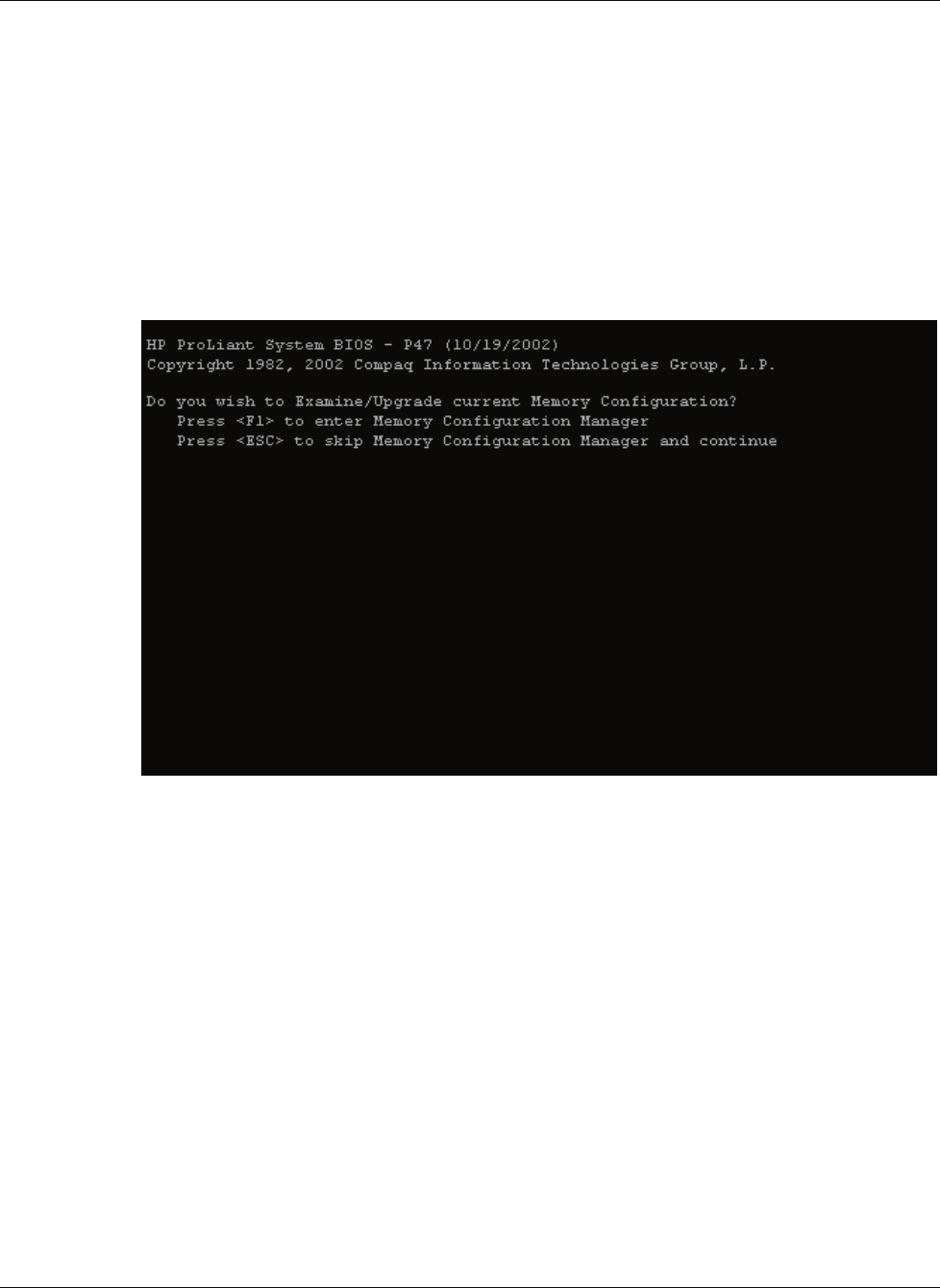
The system briefly displays the F1 prompt to open the Memory Configuration Manager.
Figure 2-6: System F1 prompt
2-12 HP ProLiant DL740 Server Maintenance and Service Guide
HP CONFIDENTIAL Codename: Jethro Part Number: 270853-004 Last Saved On: 2/10/04 3:46 PM