
ProLiant DL740 Server Maintenance and Service Guide


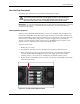


Table Of Contents
- HP ProLiant DL740 Server Maintenance and Service Guide
- Notice
- Contents
- About This Guide
- Chapter 1: Illustrated Parts Catalog
- Chapter 2: Service Preparation
- Chapter 3: Chassis Components Removal and Replacement Procedures
- Chapter 4: Host Module Removal and Replacement Procedures
- Chapter 5: Power and Media Module Removal and Replacement Procedures
- Chapter 6: Diagnostic Tools
- Chapter 7: Connectors, Switches, and LED Indicators
- Connectors
- System Board
- Switches
- LED Indicators
- System Power LED Switch
- Unit Identification LED Switches (Front and Rear)
- System Interconnect LED Indicators
- System Attention LED Indicators
- System Activity LED Indicators
- Hot-Plug SCSI Hard Drive LED Indicators
- Power Supply LED Indicators
- Hot-Plug Fan LED Indicators
- PCI Hot Plug LED Indicators
- Memory Cartridge LED Indicators
- DIMM Status LED Indicators
- Chapter 8: Physical, Operating, and Performance Specifications
- Index

Service Preparation
To service the HP ProLiant DL740 server, you might need the following:
• Flat-blade screwdriver (4 mm)
• Torx T-15 screwdriver
• T8 screwdriver
• Phillips screwdriver
• HP SmartStart CD:
— Drive Array Advanced Diagnostics (DAAD) software
— Array Diagnostics Utility (ADU) software
— ROM-Based Inspect Utility
— ROM-Based Diagnostics
System Interconnect LEDs
The system interconnect LEDs on the ProLiant DL740 server provide a closed-loop checking
mechanism for verifying proper component mating and interconnections between critical
server components. LEDs inside the front of the server provide visual assistance in isolating
components to check if the server will not power up due to a component or module that is not
fully installed. If a status indicator LED is illuminated, reseat the component represented by
the LED. Refer to the hood labels for component location. See Chapter 7 for more
information.
Hot-Plug Procedures
You can perform some service procedures without powering down the server. Before
performing hot-plug procedures, observe the following guidelines:
• For hot-plug fan procedures, be sure that the fan zone is fully populated.
• For hot-plug power supply procedures, be sure that a redundant power supply is installed
and connected to a power source.
• For hot-plug drive procedures, determine whether the drive is part of an array. For more
information, refer to the “Hot Plug SCSI Hard Drive Replacement Guidelines” in the HP
Servers Troubleshooting Guide.
• For hot-plug expansion board procedures, ensure that the proper drivers for the PCI Hot
Plug functionality are installed. For more information, refer to the HP ProLiant DL740
Server User Guide.
The access panels can be removed while the server is powered up without causing a system
shutdown. When the server is in Standby mode, portions of the power supply, auxiliary
power (+5 V), and some internal circuitry remain active.
2-8 HP ProLiant DL740 Server Maintenance and Service Guide
HP CONFIDENTIAL Codename: Jethro Part Number: 270853-004 Last Saved On: 2/10/04 3:46 PM