
ProLiant DL580 Generation 3 Server Maintenance and Service Guide
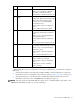
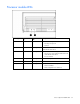
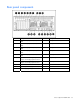
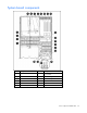
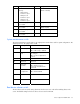
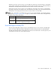
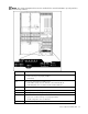
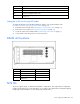
Table Of Contents
- HP ProLiant DL580 Generation 3 Server Maintenance and Service Guide
- Notice
- Contents
- Illustrated parts catalog
- Removal and replacement procedures
- Required tools
- Safety considerations
- Preparation procedures
- Removing the front bezel
- Removing a media drive blank
- Removing a media drive
- Removing the processor module
- Removing a processor
- Removing a PPM
- Removing a PCI latch
- Removing a PCI retaining clip
- Removing the PCI-X Hot Plug basket
- Removing a non-hot-plug expansion board
- Removing the PCI-X Hot Plug mezzanine option
- Removing the PCI Express mezzanine option
- Recovering data from the BBWC
- Removing the BBWC battery pack
- Removing the BBWC cache module
- Removing the system board
- Removing the system battery
- Removing the media board
- Removing the SCSI backplane
- Removing the power backplane
- Removing the memory backplane
- Removing a hard drive blank
- Removing a hot-plug SCSI hard drive
- Removing a hot-plug SAS hard drive
- Removing the SAS-SATA hard drive cage
- Removing the SAS-SATA backplane
- Removing a PCI-X Hot Plug expansion board
- Removing a power supply blank
- Removing a redundant hot-plug power supply
- Replacing hot-plug fans
- Memory overview
- Diagnostic tools
- SmartStart software
- SmartStart Scripting Toolkit
- HP Instant Support Enterprise Edition
- Option ROM Configuration for Arrays
- HP ROM-Based Setup Utility
- ROMPaq utility
- System Online ROM flash component utility
- Integrated Management Log
- Integrated Lights-Out technology
- Automatic Server Recovery
- HP Systems Insight Manager
- HP Insight Diagnostics
- USB support
- Troubleshooting the system using port 85 codes
- Server component identification
- Front panel components
- Front panel LEDs and buttons
- Memory board components and LEDs
- Processor module LEDs
- Rear panel components
- Rear panel LEDs and buttons
- Power supply LEDs
- System board components
- DIMM slot locations
- SCSI IDs
- Hot-plug SCSI hard drive LEDs
- Hot-plug SCSI hard drive LED combinations
- SATA or SAS IDs
- SATA or SAS hard drive LEDs
- SAS and SATA hard drive LED combinations
- Fan locations
- Hot-plug fan LEDs
- BBWC LEDs
- Server cabling
- Specifications
- Acronyms and abbreviations
- Index

Server component identification 77
Item Description Item Description
7
Connectors for one of the
following:
• PCI-X Hot Plug
mezzanine option
• PCI Express x4
mezzanine option
• PCI Express x8
mezzanine option
18
Boot device selector switch
(default = FLP TOP)
8
PCI-X non-hot-plug slot 3, 64-
bit/133-MHz
19 SCSI port A
9
PCI-X, non-hot-plug slot 4, 64-
bit/133-MHz
20
SCSI simplex/duplex switch
(default = duplex)
10
PCI-X, non-hot-plug slot 5, 64-
bit/133-MHz
21 Port 84/85 code switch
11
PCI-X, non-hot-plug slot 6, 64-
bit/100-MHz
22 SCSI port B
System maintenance switch
The system maintenance switch (SW1) is an eight-position switch that is used for system configuration. The
default position for all eight positions is Off.
Position Description Function
S1 iLO Security Off = iLO security is enabled
On = iLO security is disabled
S2
Configuration
lock
Off = System configuration can
be changed
On = System configuration is
locked
S3 Reserved Reserved
S4 Reserved Reserved
S5
Password
protection
override
Off = No function
On = Clears power-on
password and administrator
password
S6
Invalidate
configuration
Off = Normal
On = Clears NVRAM
S7 Reserved Reserved
S8 Reserved Reserved
Boot device selector switch
The boot device selector switch setting determines the device access order of the multibay drives in the
server. The default setting for the boot device selector switch is FLP TOP.