
ProLiant DL580 Generation 3 Server Maintenance and Service Guide
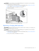
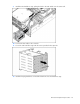
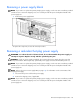
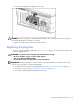
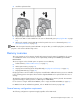
Table Of Contents
- HP ProLiant DL580 Generation 3 Server Maintenance and Service Guide
- Notice
- Contents
- Illustrated parts catalog
- Removal and replacement procedures
- Required tools
- Safety considerations
- Preparation procedures
- Removing the front bezel
- Removing a media drive blank
- Removing a media drive
- Removing the processor module
- Removing a processor
- Removing a PPM
- Removing a PCI latch
- Removing a PCI retaining clip
- Removing the PCI-X Hot Plug basket
- Removing a non-hot-plug expansion board
- Removing the PCI-X Hot Plug mezzanine option
- Removing the PCI Express mezzanine option
- Recovering data from the BBWC
- Removing the BBWC battery pack
- Removing the BBWC cache module
- Removing the system board
- Removing the system battery
- Removing the media board
- Removing the SCSI backplane
- Removing the power backplane
- Removing the memory backplane
- Removing a hard drive blank
- Removing a hot-plug SCSI hard drive
- Removing a hot-plug SAS hard drive
- Removing the SAS-SATA hard drive cage
- Removing the SAS-SATA backplane
- Removing a PCI-X Hot Plug expansion board
- Removing a power supply blank
- Removing a redundant hot-plug power supply
- Replacing hot-plug fans
- Memory overview
- Diagnostic tools
- SmartStart software
- SmartStart Scripting Toolkit
- HP Instant Support Enterprise Edition
- Option ROM Configuration for Arrays
- HP ROM-Based Setup Utility
- ROMPaq utility
- System Online ROM flash component utility
- Integrated Management Log
- Integrated Lights-Out technology
- Automatic Server Recovery
- HP Systems Insight Manager
- HP Insight Diagnostics
- USB support
- Troubleshooting the system using port 85 codes
- Server component identification
- Front panel components
- Front panel LEDs and buttons
- Memory board components and LEDs
- Processor module LEDs
- Rear panel components
- Rear panel LEDs and buttons
- Power supply LEDs
- System board components
- DIMM slot locations
- SCSI IDs
- Hot-plug SCSI hard drive LEDs
- Hot-plug SCSI hard drive LED combinations
- SATA or SAS IDs
- SATA or SAS hard drive LEDs
- SAS and SATA hard drive LED combinations
- Fan locations
- Hot-plug fan LEDs
- BBWC LEDs
- Server cabling
- Specifications
- Acronyms and abbreviations
- Index

Removal and replacement procedures 50
4.
Install the replacement fan.
5. Repeat to replace additional fans as needed.
6. Observe the LED on each installed fan to be sure it is illuminated green ("Hot-plug fan LEDs" on page
87).
7. Observe the internal system health LED on the front panel to be sure it is illuminated green ("Front
panel LEDs and buttons" on page 69).
NOTE: If the front panel internal system health LED is not green after you install hot-plug fans, reseat the hot-
plug fan or refer to the troubleshooting section.
Memory overview
This server supports up to four memory boards. Each memory board contains four DIMM slots for a total
of 16 DIMM slots in the server. Memory can be expanded by installing PC2-3200R Registered DDR2
DRAM DIMMs.
The server supports a host of AMP options to optimize server availability:
• Advanced ECC ("Advanced ECC memory" on page 51)
• Online spare memory (on page 52)
• Hot-plug mirrored memory (dual- and quad-board) ("Hot-plug mirrored memory" on page 53)
• Hot-plug RAID memory (on page 54)
Hot-plug operations can be hot-add or hot-replace. Hot-add makes additional memory resources available
to the operating system. Hot-replace allows failed or degraded DIMMs to be replaced while the server is
running.
The maximum supported total memory for this server is 64 GB using four memory boards. The maximum
supported memory per memory board is 16 GB using four 4-GB DIMMs.
For an overview of single- and dual-rank DIMMs, refer to "Single- and dual-rank DIMMs (on page 51)."
For DIMM slot locations and bank assignments, refer to "DIMM slot locations (on page 80)."
General memory configuration requirements
The following configuration requirements apply regardless of the AMP mode.