
ProLiant DL580 Generation 3 Server Maintenance and Service Guide
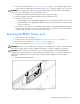
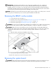
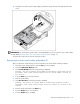
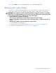
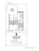
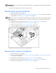
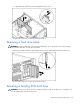
Table Of Contents
- HP ProLiant DL580 Generation 3 Server Maintenance and Service Guide
- Notice
- Contents
- Illustrated parts catalog
- Removal and replacement procedures
- Required tools
- Safety considerations
- Preparation procedures
- Removing the front bezel
- Removing a media drive blank
- Removing a media drive
- Removing the processor module
- Removing a processor
- Removing a PPM
- Removing a PCI latch
- Removing a PCI retaining clip
- Removing the PCI-X Hot Plug basket
- Removing a non-hot-plug expansion board
- Removing the PCI-X Hot Plug mezzanine option
- Removing the PCI Express mezzanine option
- Recovering data from the BBWC
- Removing the BBWC battery pack
- Removing the BBWC cache module
- Removing the system board
- Removing the system battery
- Removing the media board
- Removing the SCSI backplane
- Removing the power backplane
- Removing the memory backplane
- Removing a hard drive blank
- Removing a hot-plug SCSI hard drive
- Removing a hot-plug SAS hard drive
- Removing the SAS-SATA hard drive cage
- Removing the SAS-SATA backplane
- Removing a PCI-X Hot Plug expansion board
- Removing a power supply blank
- Removing a redundant hot-plug power supply
- Replacing hot-plug fans
- Memory overview
- Diagnostic tools
- SmartStart software
- SmartStart Scripting Toolkit
- HP Instant Support Enterprise Edition
- Option ROM Configuration for Arrays
- HP ROM-Based Setup Utility
- ROMPaq utility
- System Online ROM flash component utility
- Integrated Management Log
- Integrated Lights-Out technology
- Automatic Server Recovery
- HP Systems Insight Manager
- HP Insight Diagnostics
- USB support
- Troubleshooting the system using port 85 codes
- Server component identification
- Front panel components
- Front panel LEDs and buttons
- Memory board components and LEDs
- Processor module LEDs
- Rear panel components
- Rear panel LEDs and buttons
- Power supply LEDs
- System board components
- DIMM slot locations
- SCSI IDs
- Hot-plug SCSI hard drive LEDs
- Hot-plug SCSI hard drive LED combinations
- SATA or SAS IDs
- SATA or SAS hard drive LEDs
- SAS and SATA hard drive LED combinations
- Fan locations
- Hot-plug fan LEDs
- BBWC LEDs
- Server cabling
- Specifications
- Acronyms and abbreviations
- Index
Removal and replacement procedures 39
IMPORTANT: Be sure to set the SCSI simplex/duplex switch to the appropriate setting when replacing the
SCSI backplane.
To replace the component, reverse the removal procedure.
Removing the power backplane
1. Power down the server (on page 16).
2. Remove all power supplies ("Removing a redundant hot-plug power supply" on page 48) and power
supply blanks ("Removing a power supply blank" on page 48).
NOTE: If you remove or replace the primary hot-plug power supply, use the T-15 Torx screwdriver provided
with the server to remove the shipping screw. It is located just under the port-colored plastic handle of the
power supply unit.
3. Extend or remove the server from the rack ("Remove the server from the rack" on page 16).
4. Remove the access panel ("Removing the access panel" on page 17).
5. Remove the system cage ("Removing the system cage" on page 17).
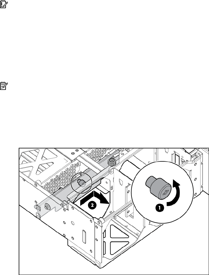
6. Loosen the thumbscrew, and remove the power backplane from the server.
To replace the component, reverse the removal procedure.
Removing the memory backplane
1. Power down the server (on page 16).
2. Remove all memory boards ("Removing a memory board" on page 58, "Removing a memory board
(non-hot-plug)" on page 57).
3. Remove the processor module ("Removing the processor module" on page 20).
4. Extend or remove the server from the rack ("Remove the server from the rack" on page 16).
5. Remove the access panel ("Removing the access panel" on page 17).