
ProLiant DL580 Generation 3 Server Maintenance and Service Guide
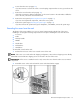
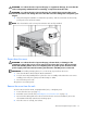
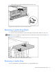
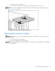
Table Of Contents
- HP ProLiant DL580 Generation 3 Server Maintenance and Service Guide
- Notice
- Contents
- Illustrated parts catalog
- Removal and replacement procedures
- Required tools
- Safety considerations
- Preparation procedures
- Removing the front bezel
- Removing a media drive blank
- Removing a media drive
- Removing the processor module
- Removing a processor
- Removing a PPM
- Removing a PCI latch
- Removing a PCI retaining clip
- Removing the PCI-X Hot Plug basket
- Removing a non-hot-plug expansion board
- Removing the PCI-X Hot Plug mezzanine option
- Removing the PCI Express mezzanine option
- Recovering data from the BBWC
- Removing the BBWC battery pack
- Removing the BBWC cache module
- Removing the system board
- Removing the system battery
- Removing the media board
- Removing the SCSI backplane
- Removing the power backplane
- Removing the memory backplane
- Removing a hard drive blank
- Removing a hot-plug SCSI hard drive
- Removing a hot-plug SAS hard drive
- Removing the SAS-SATA hard drive cage
- Removing the SAS-SATA backplane
- Removing a PCI-X Hot Plug expansion board
- Removing a power supply blank
- Removing a redundant hot-plug power supply
- Replacing hot-plug fans
- Memory overview
- Diagnostic tools
- SmartStart software
- SmartStart Scripting Toolkit
- HP Instant Support Enterprise Edition
- Option ROM Configuration for Arrays
- HP ROM-Based Setup Utility
- ROMPaq utility
- System Online ROM flash component utility
- Integrated Management Log
- Integrated Lights-Out technology
- Automatic Server Recovery
- HP Systems Insight Manager
- HP Insight Diagnostics
- USB support
- Troubleshooting the system using port 85 codes
- Server component identification
- Front panel components
- Front panel LEDs and buttons
- Memory board components and LEDs
- Processor module LEDs
- Rear panel components
- Rear panel LEDs and buttons
- Power supply LEDs
- System board components
- DIMM slot locations
- SCSI IDs
- Hot-plug SCSI hard drive LEDs
- Hot-plug SCSI hard drive LED combinations
- SATA or SAS IDs
- SATA or SAS hard drive LEDs
- SAS and SATA hard drive LED combinations
- Fan locations
- Hot-plug fan LEDs
- BBWC LEDs
- Server cabling
- Specifications
- Acronyms and abbreviations
- Index
Removal and replacement procedures 15
•
Power down the server (on page 16).
If you must remove a server from a rack or a non-hot-plug component from a server, power down the
server.
• Remove the server from the rack (on page 16).
If the rack environment, cabling configuration, or the server location in the rack makes it difficult to
service the unit, remove the server from the rack.
• Remove the access panel ("Removing the access panel" on page 17).
If you are servicing internal components, remove the access panel.
• Remove the system cage ("Removing the system cage" on page 17).
If you must remove the system board, power backplane, or the BBWC, remove the system cage.
Extending the server from the rack
The design of the server enables you to access several components through the front of the server.
Installing or accessing the following components will not require extending the server from the rack:
• Processors
• PPMs
• Memory boards
• DIMMs
• Media drive
• Diskette drive
• Hard drives
To extend the server from the rack:
1. Release the two levers on the lower outside corners of the rack.
NOTE: If the server is in a rack and in the shipping configuration, remove the two shipping screws directly
behind the levers and the two shipping screws on the rails in the rear of the server.
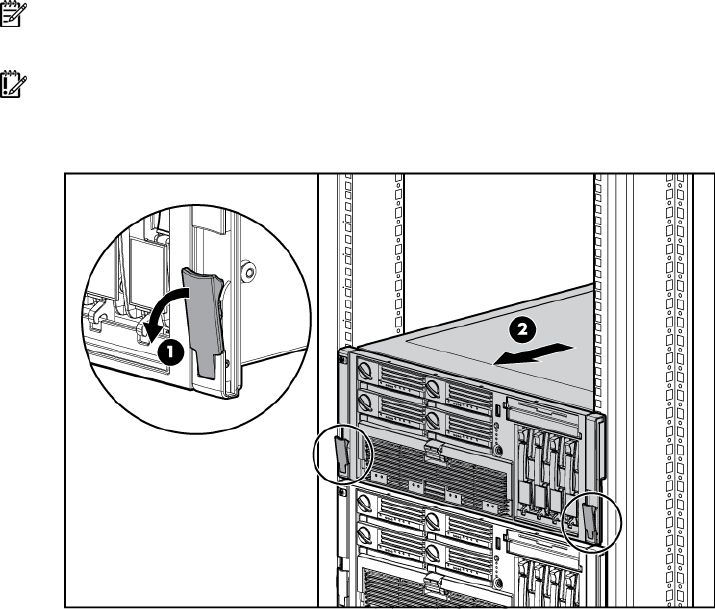
IMPORTANT: If the server is installed in a telco rack, remove the server from the rack to access internal
components.
2. Extend the server on the rack rails until the server rail-release latches engage.