
Compaq Parallel Database Cluster Model PDC/O2000 for Oracle8i and Windows 2000 Administrator Guide

2-58 Compaq Parallel Database Cluster Model PDC/O2000 for Oracle8i and Windows 2000 Administrator Guide
Compaq Confidential – Need to Know Required
Writer: John Blackburn Project: Compaq Parallel Database Cluster Model PDC/O2000 for Oracle8i and Windows 2000 Administrator Guide Comments:
Part Number: 225082-002 File Name: c-ch2 Cluster Architecture.doc Last Saved On: 6/13/01 10:21 AM
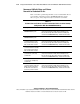
Active/Active Configuration Examples for
Redundant FC-ALs
This section describes examples of active/active configurations when two,
three, four, and five RA4000/RA4100 Arrays are present in one redundant
FC-AL of a four-node PDC/O2000 cluster. These examples represent one
method for configuring active/active configurations. They are presented here
to provide a relatively simple and consistent method for building active/active
configurations.
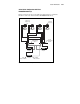
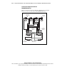
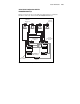
IMPORTANT: Figures 2-25 through 2-28 show active/active configurations for a
four-node cluster. Active/active configurations for clusters with two, three, five, or more
nodes are not described here. However, the illustrated active/active configuration
examples provided should supply sufficient information for building an active/standby
configuration in any PDC/O2000 cluster.
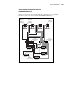
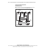
The active/active configuration examples shown in Figures 2-25 through 2-28
follow these configuration guidelines:
■ For every Fibre Host Adapter pair, the top or leftmost Fibre Host
Adapter in each node is connected to the odd-numbered Storage Hub or
FC-AL Switch (Storage Hub/FC-AL Switch #1). This is an active Fibre
Host Adapter.
■ For every Fibre Host Adapter pair, the bottom or rightmost Fibre Host
Adapter in each node is connected to the even-numbered Storage Hub or
FC-AL Switch (Storage Hub/FC-AL Switch #2). This is also an active
Fibre Host Adapter.
■ In each RA4000/RA4100 Array, the top (rack model) or right rear
(tower model) array controller is always the active controller.
■ In each RA4000/RA4100 Array, the bottom (rack model) or left rear
(tower model) array controller is always the standby controller.
■ The odd-numbered Storage Hub or FC-AL Switch (Storage Hub/FC-AL
Switch #1) is connected to the active array controller in each
odd-numbered RA4000/RA4100 Array (1, 3, and 5).
■ The odd-numbered Storage Hub or FC-AL Switch (Storage Hub/FC-AL
Switch #2) is connected to the standby array controller in each
even-numbered RA4000/RA4100 Array (2 and 4).