
Compaq Parallel Database Cluster Model PDC/O2000 for Oracle8i and Windows 2000 Administrator Guide


Cluster Architecture 2-21
■ In each RA4000/RA4100 Array, the bottom (rack model) or left rear
(tower model) array controller is always the standby controller.
■ The odd-numbered Fibre Channel SAN Switch (Fibre Channel SAN
Switch #1) is connected to the active array controller in each
RA4000/RA4100 Array.
■ The even-numbered Fibre Channel SAN Switch (Fibre Channel SAN
Switch #2) is connected to the standby array controller in each
RA4000/RA4100 Array.
NOTE: The following active/standby configurations are examples only. You are not
required to follow these configurations.
For more information about installing active/standby configurations, refer to
the following sections in Chapter 5, “Installation and Configuration”:
■ “Cabling the Fibre Host Adapters to the Storage Hubs or Switches”
■ “Cabling the Storage Hubs or Switches to the RA4000 Array
Controllers”
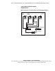
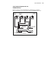
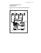
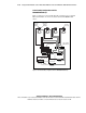
In Figures 2-6 through 2-10, active I/O path components have been shaded to
distinguish them from standby (inactive) components. Black Fibre Channel
cables identify connections between active components; gray cables identify
connections between standby components.