
Compaq Parallel Database Cluster Model PDC/O2000 for Oracle8i and Windows 2000 Administrator Guide


1-2 Compaq Parallel Database Cluster Model PDC/O2000 for Oracle8i and Windows 2000 Administrator Guide
Compaq Confidential – Need to Know Required
Writer: John Blackburn Project: Compaq Parallel Database Cluster Model PDC/O2000 for Oracle8i and Windows 2000 Administrator Guide Comments:
Part Number: 225082-002 File Name: b-ch1 Clustering Overview.doc Last Saved On: 6/13/01 10:17 AM
Clusters Defined
A cluster is an integration of software and hardware products that enables a set
of loosely coupled servers and shared storage subsystem components to
present a single system image to clients and to operate as a single system. As a
cluster, the group of servers and shared storage subsystem components offers a
level of availability and scalability far exceeding that obtained if each cluster
node operated as a stand-alone server.
The PDC/O2000 uses the Oracle8i Parallel Server software, which is a parallel
database that can distribute its workload among the cluster nodes. Refer to
Chapter 3, “Cluster Software Components” to determine the specific releases
your cluster kit supports.
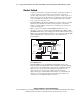
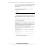
Figure 1-1 shows an example of a PDC/O2000 that includes two nodes
(ProLiant
TM
servers), two Compaq StorageWorks RAID Array 4000s or 4100s
(RA4000/RA4100 Arrays), two Compaq StorageWorks
TM
Fibre Channel Storage
Hubs, Compaq StorageWorks FC-AL Switches, or Compaq StorageWorks Fibre
Channel SAN Switches, a cluster interconnect, and a client local area
network (LAN).
Fibre Host
Adapters (2)
RA4000/4100 Array #1
RA4000/4100 Array #2
Storage
Hub/Switch #1
Switch/Hub
Client LAN
Cluster
Interconnect
Node 1 Node 2
Storage
Hub/Switch #2
Fibre Host
Adapters (2)
Figure 1-1. Example of a two-node Compaq Parallel Database
Model PDC/O2000 cluster
The PDC/O2000 can use redundant Fibre Channel Fabric Storage Area
Network (SAN) and redundant Fibre Channel Arbitrated Loop (FC-AL) SAN
topologies. These two SAN topologies support the use of multiple redundant
fabrics or loops, respectively. In the example shown in Figure 1-1, the
clustered nodes are connected to the database on the shared storage
subsystems through a redundant Fibre Channel Fabric or redundant FC-AL.
Clients access the database through the client LAN, and the cluster nodes
communicate across an Ethernet cluster interconnect.