
Compaq Parallel Database Cluster Model PDC/O2000 for Oracle8i and Windows 2000 Administrator Guide
5-10 Compaq Parallel Database Cluster Model PDC/O2000 for Oracle8i and Windows 2000 Administrator Guide
Compaq Confidential – Need to Know Required
Writer: Carol Tatick Project: Compaq Parallel Database Cluster Model PDC/O2000 for Oracle8i and Windows 2000 Administrator Guide Comments:
Part Number: 225082-002 File Name: f-ch5 Installation and Configuration.doc Last Saved On: 6/13/01 10:27 AM
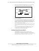
In an active/active configuration, both Fibre Host Adapters in each node are
connected to an active array controller. The number of array controllers each
Fibre Host Adapter is connected to depends on the number of
RA4000/RA4100 Arrays in the redundant Fibre Channel Fabric or redundant
FC-AL. For more information, see Chapter 2, “Cluster Architecture.”
In a PDC/O2000, each RA4000/RA4100 Array has two RA4000 Array
Controllers, one active and one standby. In some RA4000/RA4100 Arrays, the
top RA4000 Array Controller defaults to be the active array controller and in
other cases the bottom RA4000 Array Controller defaults to be the active array
controller. This default can be changed using Secure Path Manager.
NOTE: RA4000/RA4100 Arrays are available in rack and tower models. RA4000 Array
Controllers in rack models are located in top rear and bottom rear slots; in tower models,
the array controllers are located in right rear and left rear slots. The right rear and left rear
slots in tower models correspond to the top and bottom slots, respectively, in rack
models. The examples in this guide show the array controller locations in rack models.
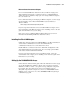
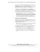
Cabling an Active/Standby Configuration
In an active/standby configuration, Storage Hub/Switch #1 connects to active
RA4000 Array Controllers and Storage Hub/Switch #2 connects to standby
RA4000 Array Controllers. The cabling instructions are the same for any
number of RA4000/RA4100 Arrays.
NOTE: When defining the active array controllers as instructed later in this chapter, make
the top array controller in each RA4000/RA4100 Array the active controller.
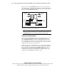
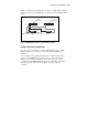
To cable the Storage Hubs, FC-AL Switches, or Fibre Channel SAN Switches
to the RA4000 Array Controllers in an active/standby configuration:
1. Using Fibre Channel cables, connect Storage Hub/Switch #1 to the top
(active) RA4000 Array Controller in each RA4000/RA4100 Array.
2. Using Fibre Channel cables, connect Storage Hub/Switch #2 to the
bottom (standby) RA4000 Array Controller in each RA4000/RA4100
Array.