HP ProLiant DL560 Server Maintenance and Service Guide January 2004 (Third Edition) Part Number 303206-003
© 2004 Hewlett-Packard Development Company, L.P. Microsoft, Windows, and Windows NT are trademarks of Microsoft Corporation in the U.S. and other countries. Intel and Pentium are trademarks of Intel Corporation in the U.S. and other countries. Hewlett-Packard Company shall not be liable for technical or editorial errors or omissions contained herein. The information in this document is provided “as is” without warranty of any kind and is subject to change without notice.
Contents Illustrated Parts Catalog 7 Mechanical Components...................................................................................................................... 7 System Components............................................................................................................................. 8 Removal and Replacement Procedures 13 Safety Considerations ........................................................................................................................
HP ProLiant DL560 Server Maintenance and Service Guide Battery................................................................................................................................................ 48 SCSI Cable......................................................................................................................................... 49 SCSI Backplane .................................................................................................................................
Contents 5 Hot-Plug SCSI Hard Drive LEDs ...................................................................................................... 89 Hot-Plug SCSI Hard Drive LED Combinations................................................................................. 90 PCI Riser Cage LED .......................................................................................................................... 91 Remote Management Connector.................................................................
Illustrated Parts Catalog In This Section Mechanical Components ................................................................................................................7 System Components .......................................................................................................................
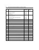
HP ProLiant DL560 Server Maintenance and Service Guide System Components Item Description Assembly Part Number Spare Part Number System Components 6 Hot-plug fan, 60 mm 289596-001 310795-001 7 Hot-plug power supply, 550 W 280126-001 300892-001 8 PCI riser cage 313004-001 295012-001 9 Processor assembly a) Intel Pentium processor, Xeon MP, 2.0-GHz/1-MB L3 cache — 327839-001 b) Intel Pentium processor, Xeon MP, 2.
Illustrated Parts Catalog Item 10 Description Assembly Part Number Spare Part Number c) Intel Pentium processor, Xeon MP, 2.8-GHz/2-MB L3 cache — 327841-001 d) Intel Pentium processor, Xeon MP, 2.2 GHz/2-MB L3* — 352311-001 e) Intel Pentium processor, Xeon MP, 2.7 GHz/2-MB L3* — 352312-001 f) Intel Pentium processor, Xeon MP, 3.
HP ProLiant DL560 Server Maintenance and Service Guide Item Description Assembly Part Number Spare Part Number 25 Hardware kit * — 228527-001 a) Screws, T-15, flathead 228213-001 — b) Expansion slot cover 228072-001 — c) Screws, 6-32 192308-009 — Plastics kit — 314688-001 a) PCI slot release lever * 228194-001 — b) Battery Backed-Write Cache Enabler bracket 302925-001 — c) Blank, tape drive * 218512-001 — 27 AC power cord, IEC-IEC 10 ft.
Illustrated Parts Catalog Item Description * Not shown Assembly Part Number Spare Part Number 11
Removal and Replacement Procedures In This Section Safety Considerations ...................................................................................................................14 Preparation Procedures .................................................................................................................15 Hot-Plug SCSI Hard Drive ...........................................................................................................19 Hard Drive Blank ..........................
HP ProLiant DL560 Server Maintenance and Service Guide You need the following items for some procedures: • Torx T-15 screwdriver (provided with the server) • Diagnostics Utility Safety Considerations Before performing service procedures, review all the safety information. Preventing Electrostatic Discharge To prevent damaging the system, be aware of the precautions you need to follow when setting up the system or handling parts.
Removal and Replacement Procedures 15 WARNING: To reduce the risk of electric shock or damage to the equipment: • Do not disable the power cord grounding plug. The grounding plug is an important safety feature. • Plug the power cord into a grounded (earthed) electric outlet that is easily accessible at all times. • Unplug the power cord from the power supply to disconnect power to the equipment. • Do not route the power cord where it can be walked on or pinched by items placed against it.
HP ProLiant DL560 Server Maintenance and Service Guide • Power down the server ("Powering Down the Server" on page 16). If you must remove a server from a rack or a non-hot-plug component from a server, power down the server. • Remove the server from the rack ("Removing the Server from the Rack" on page 18). If the rack environment, cabling configuration, or the server location in the rack creates awkward conditions, remove the server from the rack.
Removal and Replacement Procedures 17 5. If the server is installed in a rack, locate the server by identifying the illuminated rear UID LED button. 6. Disconnect the power cords. The system is now without power. Extending the Server from the Rack 1. Loosen the thumbscrews that secure the server faceplate to the front of the rack. 2. Grasping the handles on the front bezel, extend the server on the rack rails until the server rail-release latches engage.
HP ProLiant DL560 Server Maintenance and Service Guide a. Press the server rail-release latches and slide the server fully into rack. b. Secure the server by tightening the thumbscrews. Removing the Server from the Rack To remove the server from a Compaq branded, telco, or third-party rack: 1. Power down the server ("Powering Down the Server" on page 16). 2. Loosen the front panel thumbscrews that secure the server faceplate to the front of the rack. 3.
Removal and Replacement Procedures CAUTION: Do not operate the server for long periods without the access panel. Operating the server without the access panel results in improper airflow and improper cooling that can lead to thermal damage. 1. Power down the server if performing a non-hot-plug installation or maintenance procedure ("Powering Down the Server" on page 16). 2. Extend the server from the rack, if applicable ("Extending the Server from the Rack" on page 17). 3.
HP ProLiant DL560 Server Maintenance and Service Guide To replace the component, reverse the removal procedure. Hard Drive Blank To remove the component: CAUTION: To prevent improper cooling and thermal damage, do not operate the server unless all bays are populated with either a component or a blank. To replace the blank, slide the blank into the bay until it locks into place. CD-ROM Drive To remove the component: 1. Power down the server ("Powering Down the Server" on page 16).
Removal and Replacement Procedures 21 2. Remove the CD-ROM drive. To replace the CD-ROM drive, slide the drive into the bay until the drive is fully seated. CD-ROM Drive Blank To remove the component: CAUTION: To prevent improper cooling and thermal damage, do not operate the server unless all bays are populated with either a component or a blank.
HP ProLiant DL560 Server Maintenance and Service Guide IMPORTANT: The ejector button is recessed to prevent accidental ejection; it may be helpful to use the Torx T-15 tool on the back of the server or similar shaped object to access the button. To replace the blank, slide the blank into the bay until it locks into place.
Removal and Replacement Procedures 23 Universal Hot-Plug Tape Drive To remove the component: CAUTION: To prevent improper cooling and thermal damage, do not operate the server unless all bays are populated with either a component or a blank. To replace the Universal Hot-Plug tape drive, slide the drive into the bay until it locks into place. Tape Drive Blank To remove the component: 1.
HP ProLiant DL560 Server Maintenance and Service Guide 3. Remove the tape drive blank. a. Reach underneath and squeeze the middle of the tape drive blank (1). b. Pull the blank out of the bay (2). 4. To replace the blank, slide the blank into the bay until it locks into place. Hot-Plug Power Supply To remove the component: 1. Unlock the hinge on the cable management arm and swing the arm away from the power supply area. 2.
Removal and Replacement Procedures 3. Remove the shipping screw and then the hot-plug power supply. IMPORTANT: The power supply shipping screw is not required for server operation. It is only required for shipping. To replace a hot-plug power supply: 1. Remove the protective cover from the connector pins on the power supply. WARNING: To reduce the risk of electric shock or damage to the equipment, do not connect the power cord to the power supply until the power supply is installed.
HP ProLiant DL560 Server Maintenance and Service Guide 2. Slide the power supply into the power supply bay. 3. Connect the power cord to the power supply. 4. Route the power cord through the cable management arm or power cord anchor. NOTE: If using the power cord anchor, be sure to leave enough slack in the power cord so that the redundant power supply can be removed without disconnecting the power cord from the primary power supply. 5. Lock the cable management arm into the operating position.
Removal and Replacement Procedures 27 1. Slide the power supply blank into the bay until it locks into place. 2. Swing the cable management arm into place and lock it. Hot-Plug Fan To remove the component: 1. Extend or remove the server from the rack ("Extending the Server from the Rack" on page 17, "Removing the Server from the Rack" on page 18). 2. Remove the access panel ("Removing the Access Panel" on page 18). 3.
HP ProLiant DL560 Server Maintenance and Service Guide CAUTION: Do not operate the server for long periods without the access panel. Operating the server without the access panel results in improper airflow and improper cooling that can lead to thermal damage. IMPORTANT: For optimum cooling, install fans in all primary fan locations. For more information, refer to the previous fan locations table. To replace the component, reverse the removal procedure. Front Bezel To remove the component: 1.
Removal and Replacement Procedures 5. Remove the front bezel. To replace the component, reverse the removal procedure. Front Fan Module To remove the component: 1. Power down the server ("Powering Down the Server" on page 16). 2. Extend or remove the server from the rack ("Extending the Server from the Rack" on page 17, "Removing the Server from the Rack" on page 18). 3. Remove the access panel ("Removing the Access Panel" on page 18).
HP ProLiant DL560 Server Maintenance and Service Guide 4. Lift the removable media tray. 5. Remove the fan module. NOTE: Fans do not have to be removed to install or remove the fan module. To replace the front fan bracket, reverse the removal steps and press down on the top of each fan to be sure it is seated properly.
Removal and Replacement Procedures 31 Battery-Backed Write Cache Enabler Bracket To remove the component: 1. Power down the server ("Powering Down the Server" on page 16). 2. Extend or remove the server from the rack ("Extending the Server from the Rack" on page 17, "Removing the Server from the Rack" on page 18). 3. Remove the access panel ("Removing the Access Panel" on page 18). 4. Remove the battery module bracket: a.
HP ProLiant DL560 Server Maintenance and Service Guide Battery-Backed Write Cache Enabler To remove the component: 1. Power down the server ("Powering Down the Server" on page 16). 2. Extend or remove the server from the rack ("Extending the Server from the Rack" on page 17, "Removing the Server from the Rack" on page 18). 3. Remove the access panel ("Removing the Access Panel" on page 18). 4.
Removal and Replacement Procedures 1. Power down the server ("Powering Down the Server" on page 16). 2. Extend the server from the rack, if applicable ("Extending the Server from the Rack" on page 17). 3. Remove the access panel ("Removing the Access Panel" on page 18). 4. Disconnect any internal or external cables connected to any existing expansion boards. 5. Remove the PCI riser cage. To replace the component, reverse the removal procedure. Expansion Board To remove the component: 1.
HP ProLiant DL560 Server Maintenance and Service Guide 3. Unlock the PCI retaining clip. CAUTION: To prevent improper cooling and thermal damage, do not operate the server unless all PCI slots have either an expansion slot cover or an expansion board installed. 4. Remove the expansion board. To replace the component, reverse the removal procedure.
Removal and Replacement Procedures Expansion Slot Cover To remove the component: 1. Power down the server ("Powering Down the Server" on page 16). 2. Extend or remove the server from the rack ("Extending the Server from the Rack" on page 17, "Removing the Server from the Rack" on page 18). 3. Remove the access panel ("Removing the Access Panel" on page 18). 4. Remove the PCI riser cage ("PCI Riser Cage" on page 32).
HP ProLiant DL560 Server Maintenance and Service Guide 3. Remove the access panel ("Removing the Access Panel" on page 18). 4. Remove the PCI riser cage ("PCI Riser Cage" on page 32). CAUTION: To prevent damage to the server or expansion boards, power down the server and remove all AC power cords before removing or installing the PCI riser cage. 5. Remove the expansion board from the slot, if installed ("Expansion Board" on page 33). 6.
Removal and Replacement Procedures 8. Remove the PCI slot release lever. To replace the component, reverse the removal procedure. Power Module To remove the component: 1. Power down the server ("Powering Down the Server" on page 16). 2. Extend or remove the server from the rack ("Extending the Server from the Rack" on page 17, "Removing the Server from the Rack" on page 18). 3. Remove the access panel ("Removing the Access Panel" on page 18).
HP ProLiant DL560 Server Maintenance and Service Guide 4. Disconnect internal power cables. 5. Remove power module. To replace the component, reverse the removal procedure.
Removal and Replacement Procedures 39 DC Converter Module To remove the component: NOTE: You do not have to remove the DC converter module to remove the power module. 1. Power down the server ("Powering Down the Server" on page 16). 2. Extend or remove the server from the rack ("Extending the Server from the Rack" on page 17, "Removing the Server from the Rack" on page 18). 3. Remove the access panel ("Removing the Access Panel" on page 18). 4. Disconnect internal power cables. 5.
HP ProLiant DL560 Server Maintenance and Service Guide 6. Remove the DC converter module. Power Button/LED Board To remove the component: 1. Power down the server ("Powering Down the Server" on page 16). 2. Extend or remove the server from the rack ("Extending the Server from the Rack" on page 17, "Removing the Server from the Rack" on page 18). 3. Remove the access panel ("Removing the Access Panel" on page 18).
Removal and Replacement Procedures 4. Lift the removable media tray. 5. Remove the front fan module.
HP ProLiant DL560 Server Maintenance and Service Guide 6. Remove the screws from the front bezel to expose the power button/LED board. 7. Remove the power button/LED board. To replace the component, reverse the removal procedure.
Removal and Replacement Procedures 43 DIMMs To remove the component: 1. Power down the server ("Powering Down the Server" on page 16). 2. Extend or remove the server from the rack ("Extending the Server from the Rack" on page 17, "Removing the Server from the Rack" on page 18). 3. Remove the access panel ("Removing the Access Panel" on page 18). NOTE: The server ships with at least two DIMMs installed in DIMM slots 1A and 2A. 4. Remove the DIMM.
HP ProLiant DL560 Server Maintenance and Service Guide Processor To remove the component: 1. Power down the server ("Powering Down the Server" on page 16). 2. Extend or remove the server from the rack ("Extending the Server from the Rack" on page 17, "Removing the Server from the Rack" on page 18). 3. Remove the access panel ("Removing the Access Panel" on page 18). 4. Lift the removable media tray.
Removal and Replacement Procedures CAUTION: Failure to open the processor locking lever completely prevents the processor from seating during installation, leading to hardware damage. CAUTION: To prevent possible server malfunction and damage to the equipment, do not mix processors of different types. CAUTION: To prevent possible server malfunction or damage to the equipment, be sure to align the processor pins with the corresponding holes in the socket.
HP ProLiant DL560 Server Maintenance and Service Guide CAUTION: To prevent possible server malfunction or damage to the equipment, be sure to completely close the processor locking lever. PPM To remove the component: 1. Power down the server ("Powering Down the Server" on page 16). 2. Extend or remove the server from the rack ("Extending the Server from the Rack" on page 17, "Removing the Server from the Rack" on page 18). 3. Remove the access panel ("Removing the Access Panel" on page 18).
Removal and Replacement Procedures Smart Array 5i Plus Memory Module To remove the component: 1. Power down the server ("Powering Down the Server" on page 16). 2. Extend or remove the server from the rack ("Extending the Server from the Rack" on page 17, "Removing the Server from the Rack" on page 18). 3. Remove the access panel ("Removing the Access Panel" on page 18). 4. Remove the PCI riser cage ("PCI Riser Cage" on page 32).
HP ProLiant DL560 Server Maintenance and Service Guide CAUTION: To prevent damage to the memory module during installation, be sure the memory module is fully inserted before pressing down. Battery If the server no longer automatically displays the correct date and time, you may need to replace the battery that provides power to the real-time clock. Under normal use, battery life is 5 to 10 years.
Removal and Replacement Procedures 5. Remove the battery. IMPORTANT: Replacing the system board battery resets the system ROM to its default configuration. After replacing the battery, reconfigure the system through RBSU. To replace the component, reverse the removal procedure. For more information about battery replacement or proper disposal, contact an authorized reseller or authorized service provider. SCSI Cable To remove the component: 1.
HP ProLiant DL560 Server Maintenance and Service Guide 4. Disconnect and remove the SCSI cable. To replace the component, reverse the removal procedure. SCSI Backplane To remove the component: 1. Power down the server ("Powering Down the Server" on page 16). 2. Extend or remove the server from the rack ("Extending the Server from the Rack" on page 17, "Removing the Server from the Rack" on page 18). 3. Remove the access panel ("Removing the Access Panel" on page 18). 4.
Removal and Replacement Procedures 6. Disconnect cables connected to the SCSI backplane. 7. Remove the SCSI backplane. To replace the component, reverse the removal procedure. Removable Media Tray To remove the component: 1. Power down the server ("Powering Down the Server" on page 16).
HP ProLiant DL560 Server Maintenance and Service Guide 2. Extend or remove the server from the rack ("Extending the Server from the Rack" on page 17, "Removing the Server from the Rack" on page 18). 3. Remove the access panel ("Removing the Access Panel" on page 18). 4. Lift the removable media tray. 5. Disconnect cables from the system board.
Removal and Replacement Procedures 6. Remove the removable media tray. Peripheral Board To remove the component: 1. Power down the server ("Powering Down the Server" on page 16). 2. Extend or remove the server from the rack ("Extending the Server from the Rack" on page 17, "Removing the Server from the Rack" on page 18). 3. Remove the access panel ("Removing the Access Panel" on page 18). 4. Remove the power module ("Power Module" on page 37). 5. Remove the PCI riser cage ("PCI Riser Cage" on page 32).
HP ProLiant DL560 Server Maintenance and Service Guide 6. Release the peripheral board from the system board. 7. Remove the peripheral board. System Board To remove the component: 1. Power down the server ("Powering Down the Server" on page 16).
Removal and Replacement Procedures 55 2. Extend or remove the server from the rack ("Extending the Server from the Rack" on page 17, "Removing the Server from the Rack" on page 18). 3. Remove the access panel ("Removing the Access Panel" on page 18). 4. Remove the PCI riser cage ("PCI Riser Cage" on page 32). CAUTION: To prevent damage to the server or expansion boards, power down the server and remove all AC power cords before removing or installing the PCI riser cage. 5.
HP ProLiant DL560 Server Maintenance and Service Guide 12. Remove the system board thumbscrew. 13. Identify the alignment keys and keyhole locations.
Removal and Replacement Procedures 14. Remove the system board. NOTE: The system board spare kit does not includes DIMMs, processors, PPMs, or the Smart Array 5i memory module. To replace the component, reverse the removal procedure. IMPORTANT: If replacing the system board or clearing NVRAM, you must re-enter the server serial number through RBSU ("Re-Entering the Server Serial Number" on page 58). Rear Fan Bracket To remove the component: 1. Remove the system board ("System Board" on page 54).
HP ProLiant DL560 Server Maintenance and Service Guide 2. Remove the rear fan bracket. To replace the component, reverse the removal procedure. Re-Entering the Server Serial Number After you replace the system board or clear NVRAM, you must re-enter the server serial number. 1. During the server startup sequence, press the F9 key to access RBSU. 2. Select the System Options menu. 3. Select Serial Number.
Removal and Replacement Procedures 8. Press the F10 key to confirm exiting RBSU. The server will automatically reboot.
Diagnostic Tools In This Section Automatic Server Recovery..........................................................................................................61 Insight Manager 7.........................................................................................................................62 Integrated Management Log.........................................................................................................62 Integrated Lights-Out Technology ..................................
HP ProLiant DL560 Server Maintenance and Service Guide Insight Manager 7 Insight Manager 7 is a Web-based application that allows system administrators to accomplish normal administrative tasks from any remote location, using a Web browser. Insight Manager 7 provides device management capabilities that consolidate and integrate management data from HP and third-party devices.
Diagnostic Tools 63 Integrated Lights-Out Technology Integrated Lights-Out is a standard component of selected ProLiant servers that provides server health and remote server manageability. The iLO subsystem includes an intelligent microprocessor, secure memory, and a dedicated network interface. This design makes iLO independent of the host server and its operating system.
HP ProLiant DL560 Server Maintenance and Service Guide HP recommends using DNS/DHCP with iLO to simplify installation. If DNS/DHCP cannot be used, use the following procedure to disable DNS/DHCP and to configure the IP address and the subnet mask: 1. Restart or power up the server. 2. Press the F8 key when prompted during POST. The iLO RBSU runs. 3. Enter a valid iLO user ID and password with the appropriate iLO privileges (Administer User Accounts, Configure iLO Settings).
Diagnostic Tools 65 ProLiant Essentials Rapid Deployment Pack The ProLiant Essentials Rapid Deployment Pack software is the preferred method for rapid, high-volume server deployments. The Rapid Deployment Pack software integrates two powerful products: Altiris eXpress Deployment Server and the ProLiant Integration Module.
HP ProLiant DL560 Server Maintenance and Service Guide The ROMPaq utility checks the system and provides a choice (if more than one exists) of available ROM revisions. This procedure is the same for both system and option ROMPaq utilities. For more information about the ROMPaq utility, refer to the HP website (http://www.hp.com/servers/manage).
Diagnostic Tools 67 • Create and copy standard server configuration scripts using the SmartStart Scripting Toolkit and Configuration Replication Utility. • Test server hardware using the Insight Diagnostics Utility. • Update the latest system or option ROM using the ROM Update Utility. • Install software drivers directly from the CD. With systems that have internet connection, the SmartStart Autorun Menu provides access to the complete list of ProLiant System Software on the website.
Specifications In This Section Server Dimensions and Weight ....................................................................................................69 Environmental Specifications.......................................................................................................69 Hot-Plug Power Supply Calculations ...........................................................................................70 DDR SDRAM DIMM Specifications.....................................................
HP ProLiant DL560 Server Maintenance and Service Guide Relative humidity (noncondensing) Operating 10% to 90% Non-operating 5% to 95% NOTE: Storage maximum humidity of 95% is based on a maximum temperature of 45°C (113°F). Altitude maximum for storage corresponds to a pressure minimum of 70 KPa.
Specifications Item Description Depth 130 mm (5.1 in) LEDs (front panel) Green = On Read/write capacity per diskette High density 1.
HP ProLiant DL560 Server Maintenance and Service Guide Item Description Capacity 550 MB (mode 1, 12 cm) 640 MB (mode 2, 12 cm) Block size 2368, 2352 bytes (mode 0) 2352, 2340, 2336, 2048 bytes (mode 1) 2352, 2340, 2336, 2048 bytes (mode 2) Dimensions Height 12.7 mm (0.50 inch) Depth 132.08 mm (5.20 inch) Width 132.08 mm (5.20 inch) Weight 0.34 kg (0.75 lb) Data transfer rate Sustained 150 KB/s (sustained 1X), 1500/3600 KB/s (10X to 24X) Burst 16.
Specifications Item Description Operating conditions Temperature 5°C to 45°C (41°F to 118°F) Humidity 5% to 90% 73
Server Component Identification In This Section Front Panel Components ..............................................................................................................75 Front Panel LEDs and Buttons .....................................................................................................76 Rear Panel Components................................................................................................................78 Rear Panel LEDs and Buttons ...........................
HP ProLiant DL560 Server Maintenance and Service Guide Item Description 1 SCSI hard drive bay 1 (SCSI ID 0) 2 SCSI hard drive bay 2 (SCSI ID 1) 3 Tape drive blank 4 Diskette drive 5 CD-ROM drive in Universal Media Bay Front Panel LEDs and Buttons Item Description Status 1 CD-ROM drive ejector button NA 2 UID LED button Blue = Activated Flashing = System remotely managed Off = Deactivated
Server Component Identification Item Description Status 3 Internal health LED Green = Normal Amber = System degraded. Refer to system board LEDs to identify component in degraded state ("System Board LEDs" on page 84). Red = System critical. Refer to system board LEDs to identify component in critical state ("System Board LEDs" on page 84).
HP ProLiant DL560 Server Maintenance and Service Guide Rear Panel Components Item Description Connector Color 1 Slot 1, 64-bit/133-MHz PCI-X, bus 3 N/A 2 Slot 2, 64-bit/100-MHz PCI-X, bus 6 N/A 3 Slot 3, 64-bit/100-MHz PCI-X, bus 6 N/A 4 NIC 1 RJ-45 connector N/A 5 NIC 2 RJ-45 connector N/A 6 Mouse connector Green 7 Keyboard connector Purple 8 iLO RJ-45 connector N/A 9 USB connectors Black 10 Serial connector Teal 11 Video connector Blue 12 AC power supply connecto
Server Component Identification Rear Panel LEDs and Buttons Item Description LED Color Status 1 RJ-45 activity LED Green On or flashing = Network activity Off = No network activity 2 RJ-45 link LED Green On = Linked to network Off = Not linked to network 3 Power supply LED Green On = Power turned on and power supply functioning properly Off = One or more of the following conditions exist: 4 UID LED button Blue • AC power unavailable • Power supply failed • Power supply in standby m
HP ProLiant DL560 Server Maintenance and Service Guide System Board Components Item Description Item Description 1 DIMM slots (1-6) 12 Processor socket 4 2 Smart Array 5i Plus Memory Module 13 System power connector 3 PPM slot 4 14 CD-ROM drive system connector 4 PPM slot 3 15 Diskette drive system connector 5 PPM slot 2 16 Power supply signal connector 6 PPM slot 1 (populated) 17 Chassis ID switch (under power module) 7 SCSI connector 18 VHDM connector (under power modu
Server Component Identification 81 NMI Switch The NMI switch allows administrators to perform a memory dump before performing a hard reset. Crash dump analysis is an essential part of eliminating reliability problems, such as hangs or crashes in operating systems, device drivers, and applications. Many crashes freeze a system, requiring you to do a hard reset. Resetting the system erases any information that would support root cause analysis.
HP ProLiant DL560 Server Maintenance and Service Guide Item Description 1 DIMM slot 1A 2 DIMM slot 2A 3 DIMM slot 3B 4 DIMM slot 4B 5 DIMM slot 5C 6 DIMM slot 6C System Maintenance Switch Position Default Function S1 Off Reserved S2 Off Off = System configuration can be changed. On = System configuration is locked. S3 Off Reserved S4 Off Off = Booting from diskette is controlled by RBSU. On = Booting from diskette is disabled.
Server Component Identification Position Default Function S5 Off Off = Power-on password is enabled. On = Power-on password is disabled. S6 Off Off = No function. On = Clear NVRAM*. S7 Off Off = iLO security is enabled. On = iLO security is disabled. S8 Off Off = Processor hot-spare boot is enabled. On = Processor hot-spare boot is disabled. NOTE: To access the redundant ROM using the system maintenance switch, refer to "Access to Redundant ROM Settings.
HP ProLiant DL560 Server Maintenance and Service Guide System Board LEDs
Server Component Identification Item LED Description Status 1 Processor 1 failure Amber = Processor failed Off = Normal 2 Processor 2 failure Amber = Processor failed Off = Normal 3 Processor 3 failure Amber = Processor failed Off = Normal 4 Processor 4 failure Amber = Processor failed Off = Normal 5 Online spare memory Amber = Failover, online spare memory in use Off = Disabled 6 DIMM 6C failure Amber = Memory failed Off = Normal 7 DIMM 5C failure Amber = Memory failed Off = Normal
HP ProLiant DL560 Server Maintenance and Service Guide Item LED Description Status 14 PPM 4 failure Amber = PPM failed Off = Normal 15 PPM 3 failure Amber = PPM failed Off = Normal 16 PPM 2 failure Amber = PPM failed Off = Normal 17 PPM 1 failure Amber = PPM failed Off = Normal 18 Fans (1 through 8) Green = Normal Off = Power off Amber = One or both of the following conditions exist: 19 System power • Fan failed or is not seated • Fan bracket is not seated Green = System power i
Server Component Identification 87 The front panel health LEDs indicate only the current hardware status. In some situations, Insight Manager 7 may report server status differently than the health LEDs because the software tracks more system attributes. System LED and Color Internal Health LED Color Status Processor failure, socket X (Amber) Red • Processor in socket X has failed. • Processor in socket X failed over to the offline spare. • Processor X is not installed in the socket.
HP ProLiant DL560 Server Maintenance and Service Guide System LED and Color Online spare memory (Amber) Internal Health LED Color Status Red The minimum fan requirements are not being met. One or more fans have failed or are missing. Amber Bank X failed over to the online spare memory bank.
Server Component Identification Hot-Plug SCSI Hard Drive LEDs Item LED Description Status 1 Activity status On = Drive activity Flashing = High activity on the drive or drive is being configured as part of an array. Off = No drive activity 2 Online status On = Drive is part of an array and is currently working. Flashing = Drive is actively online. Off = Drive is offline.
HP ProLiant DL560 Server Maintenance and Service Guide Hot-Plug SCSI Hard Drive LED Combinations Activity LED (1) Online LED (2) Fault LED (3) Interpretation On, off, or flashing On or off Flashing A predictive failure alert has been received for this drive. On, off, or flashing On On or flashing Flashing Replace the drive as soon as possible. Off The drive is online and is configured as part of an array.
Server Component Identification 91 PCI Riser Cage LED Status On = system power connected Off = system power disconnected CAUTION: To prevent damage to the server or expansion boards, power down the server and remove all AC power cords before removing or installing the PCI riser cage. Remote Management Connector The 30-pin remote management connector, located on the PCI riser cage, is used to cable the Remote Insight Lights-Out Edition II option.
HP ProLiant DL560 Server Maintenance and Service Guide Hot-Plug Fans Item Description Fan Zone 1 Fan 1 Processor 2 Fan 2 Processor 3 Fan 3 Processor 4 Fan 4 Processor
Server Component Identification Item Description Fan Zone 5 Fan 5 Processor 6 Fan 6 Processor 7 Fan 7 Processor 8 Fan 8 Processor 9 Fan 9 Power supply 10 Fan 10 Power supply 93 NOTE: For information on fan redundancy, refer to "Redundant Hot-Plug Fan Option (on page 93)." Redundant Hot-Plug Fan Option The server supports redundant hot-plug fans to provide proper airflow to the system if a primary fan fails. The server airflow is divided into two fan zones: processor and power supply.
HP ProLiant DL560 Server Maintenance and Service Guide − In a nonredundant configuration, the BIOS performs an orderly shutdown if a fan failure occurs in the processor zone or power supply zone. In a redundant configuration, the BIOS performs an orderly shutdown if two fan failures occur in the processor zone or power supply zone. − The server performs an immediate shutdown if a critical temperature level is detected.
Server Component Identification Hot-Plug Fan LED Status Green = Operating normally Amber = Failed Off = No power 95
Index A AC power supply 8, 24 access panel 7, 18 Altiris eXpress Deployment Server 65 ASR (Automatic Server Recovery) 61 ASR-2 (Automatic Server Recovery-2) 61 Automatic Server Recovery (ASR) 61 Automatic Server Recovery-2 (ASR-2) 61 auxiliary power LED 84 B battery 8, 48, 81 Battery-Backed Write Cache Enabler 8, 32 Battery-Backed Write Cache Enabler bracket 8, 31 bezel, front 7, 28 BIOS upgrade 66 blanks 7, 8, 20, 21, 23, 26 blue screen event 81 buttons 75 C cable kits 8 cables 8, 49 CD-ROM drive 8,
HP ProLiant DL560 Server Maintenance and Service Guide I illustrated parts catalog 7 iLO (Integrated Lights-Out) 63, 78, 82 iLO RBSU (Integrated Lights-Out ROM-Based Setup Utility) 63 IML (Integrated Management Log) 62 Insight Manager 7 62 Integrated Lights-Out ROM-Based Setup Utility (iLO RBSU) 63 Integrated Management Log (IML) 62 internal health LED 76, 86 K keyboard connector 78 L laser devices 71 LEDs 75 LEDs, hard drive 89 M management tools 61 mechanical components 7 memory 43 memory dump 81
Index rear panel buttons 79 rear panel connectors 78 rear panel LEDs 79 Remote ROM Flash, Smart Components 66 removable media tray 51 removal and replacement procedures 13 removing server from rack 18 resetting the system 81 riser interlock LED 84, 86 RJ-45 connectors 78 RJ-45 network connector LEDs 79 ROMPaq utility 66 S safety considerations 14 SCSI backplane 8, 50 SCSI backplane components 88 SCSI connectors 80, 88 SCSI IDs 75 serial connector 78 serial number 58 server setup 14 server warnings and cau