
HP ProLiant DL560 Server High Density Deployment


hp ProLiant DL560 server high-density deployment white paper
23
table 9: power statistics for high voltage 10-chassis non-redundant power configuration
description value
control unit current handling capacity 24 amperes
control unit load ~ 24 amperes under normal operation
(Server load in example is based on the
Power Calculator output using 4 processors,
6 GB memory, 72-GB hard drives x 2, and 2
PCI cards)
headroom current available for rack
peripherals
0 amperes
If additional infrastructure loads are
required to support the operation of the
rack, it is suggested that you add additional
PDUs or remove one or more servers to
create headroom for peripherals.
power cord used for server-to-
extension bar jumper
C13 to C14 (PN 142256-006) quantity of 1
C13 to C14 (PN 142256-007) quantity of 15
high voltage
(208VAC)
10-chassis
redundant power
configuration
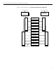
The following illustration (figure 8) shows a redundant power configuration
where high voltage (208 VAC) is distributed to ten server chassis in a rack that
receives primary and secondary power busses. A modular PDU that consists of
a control core and two extension bars is connected to each power bus. Each
control core can handle a maximum of 24 amps. Under normal operation, the
power supplies in each server would be sharing the load of the server and
each PDU would only see 50% of the full load of each server. Therefore, under
normal conditions, each PDU would be loaded to approximately 12 amps.
However, if either the primary or the secondary feed were to fail, the remaining
PDU would be loaded to the full load of each server or approximately 24 amps.
In this case, either core could be called on to provide about 24 amps to the
servers, leaving no headroom for auxiliary devices, such as KVM switches, a TFT
display, and rack monitoring devices. Refer to table 9 for power statistics for the
high voltage 10-chassis configuration.