HP ProLiant DL385 Generation 5p Server User Guide Part Number 495670-002 January 2009 (Second Edition)
© Copyright 2008, 2009 Hewlett-Packard Development Company, L.P. The information contained herein is subject to change without notice. The only warranties for HP products and services are set forth in the express warranty statements accompanying such products and services. Nothing herein should be construed as constituting an additional warranty. HP shall not be liable for technical or editorial errors or omissions contained herein. Microsoft, Windows, and Windows Server are U.S.
Contents Component identification ............................................................................................................... 7 Front panel components ............................................................................................................................. 7 Front panel LEDs and buttons ...................................................................................................................... 7 Systems Insight Display LEDs .................................
Powering up and configuring the server ..................................................................................................... 34 Registering the server............................................................................................................................... 34 Hardware options installation....................................................................................................... 35 Introduction ................................................................
ProLiant Support Packs ................................................................................................................... 62 Operating system version support .................................................................................................... 62 System Online ROM flash component utility ...................................................................................... 62 Change control and proactive notification ...........................................................
Before you contact HP.............................................................................................................................. 90 HP contact information ............................................................................................................................. 90 Customer Self Repair ............................................................................................................................... 90 Acronyms and abbreviations..............................
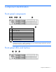
Component identification Front panel components Item Description 1 Serial number label 2 Systems Insight Display 3 Video connector 4 USB connectors (2) 5 Hard drive bays 6 SATA optical drive bay 7 Quick release levers (2) CAUTION: For proper cooling do not operate the server without the access panel, baffles, expansion slot covers, or blanks installed. If the server supports hot-plug components, minimize the amount of time the access panel is open.
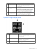
Item Description Status 1 UID LED button Blue = Activated Flashing blue = System being remotely managed Off = Deactivated 2 Health LED Green = Normal Flashing amber = System degraded. To identify a component in a degraded state, see "Systems Insight Display LEDs (on page 8)." Flashing red = System critical. To identify a component in a critical state, see "Systems Insight Display LEDs (on page 8).
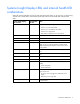
Systems Insight Display LEDs and internal health LED combinations When the internal health LED on the front panel illuminates either amber or red, the server is experiencing a health event. Combinations of illuminated system LEDs and the internal health LED indicate system status. Systems Insight Display LED and color Internal health LED color Status Processor (amber) Red One or more of the following conditions may exist: • Processor in socket X has failed.
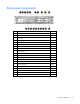
Rear panel components Item Description Color 1 PCI slot 5 — 2 PCI slot 6 — 3 PCI slot 4 — 4 PCI slot 2 — 5 PCI slot 3 — 6 PCI slot 1 — 7 Power supply 2 — 8 Power supply 2 connector — 9 Power supply 1 — 10 Power supply 1 connector — 11 USB connectors (2) Black 12 Video connector Blue 13 NIC 1 connector — 14 NIC 2 connector — 15 Mouse connector Green 16 Keyboard connector Purple 17 Serial connector — 18 iLO 2 connector — 19 NIC 3 connector — 20 NIC
Rear panel LEDs and buttons Item Description Status 1 Power supply 2 power LED Green = Normal Power supply 1 power LED Green = Normal UID LED button Blue = Activated 2 3 Off = System is off or power supply has failed. Off = System is off or power supply has failed.
Notes: • "Primary" denotes the risers are installed in the primary riser connector. • "Secondary" denotes the risers are installed in the secondary riser connector. • FL/FH denotes full-length, full-height. HL/FH denotes half-length, full-height. LP denotes low profile. • The PCIe x16 riser supports a maximum power of 225W with an HP power cable. This cable must be used for PCIe card wattages greater than 75W.
Item Description 10 System maintenance switch 11 Power supply backplane connector 12 Processor 1 socket 13 Primary riser connector 14 Secondary riser connector 15 Diagnostic LEDs 16 Processor 2 socket 17 Processor 2 DIMM slots 18 Fan 6 connector 19 Fan 5 connector 20 Fan 4 connector 21 Fan 3 connector 22 Fan 2 connector 23 Fan 1 connector System board switches System maintenance switch Position Default Function S1 Off Off = iLO 2 security is enabled.
Position Position Function On Off iLO 2 NMI functionality An NMI crash dump enables administrators to create crash dump files when a system is hung and not responding to traditional debug mechanisms. Crash dump log analysis is an essential part of diagnosing reliability problems, such as hangs in operating systems, device drivers, and applications. Many crashes freeze a system, and the only available action for administrators is to cycle the system power.
Hard drive numbering SAS and SATA hard drive LEDs Item Description 1 Fault/UID LED (amber/blue) 2 Online LED (green) SAS and SATA hard drive LED combinations Online/activity LED (green) Fault/UID LED (amber/blue) Interpretation On, off, or flashing Alternating amber and blue The drive has failed, or a predictive failure alert has been received for this drive; it also has been selected by a management application.
Online/activity LED (green) Fault/UID LED (amber/blue) Interpretation Flashing regularly (1 Hz) Amber, flashing regularly (1 Hz) Do not remove the drive. Removing a drive may terminate the current operation and cause data loss. The drive is part of an array that is undergoing capacity expansion or stripe migration, but a predictive failure alert has been received for this drive. To minimize the risk of data loss, do not replace the drive until the expansion or migration is complete.
Status On = AC power is connected. Off = AC power is disconnected. Missing = Riser is not installed and power might be connected. Battery pack LEDs Item ID Color Description 1 Green System Power LED. This LED glows steadily when the system is powered up and 12 V system power is available. This power supply is used to maintain the battery charge and provide supplementary power to the cache microcontroller. 2 Green Auxiliary Power LED. This LED glows steadily when 3.3V auxiliary voltage is detected.
LED3 pattern LED4 pattern Interpretation — One blink every two seconds The system is powered down, and the cache contains data that has not yet been written to the drives. Restore system power as soon as possible to prevent data loss. Data preservation time is extended any time that 3.3 V auxiliary power is available, as indicated by LED 2. In the absence of auxiliary power, battery power alone preserves the data. A fullycharged battery can normally preserve data for at least two days.
For more information, see "Hot-plug fan operation (on page 26).
Operations Power up the server To power up the server, press the Power On/Standby button. Power down the server WARNING: To reduce the risk of personal injury, electric shock, or damage to the equipment, remove the power cord to remove power from the server. The front panel Power On/Standby button does not completely shut off system power. Portions of the power supply and some internal circuitry remain active until AC power is removed.
3. After performing the installation or maintenance procedure, slide the server back into the rack, and then press the server firmly into the rack to secure it in place. WARNING: To reduce the risk of personal injury, be careful when pressing the server railrelease latches and sliding the server into the rack. The sliding rails could pinch your fingers.
1. Power down the server if performing a non-hot-plug installation or maintenance procedure ("Power down the server" on page 20). 2. Extend the server from the rack (on page 20). 3. Use the T-15 Torx screwdriver attached to the rear of the server to loosen the security screw on the hood latch. 4. Lift up on the hood latch handle, and then remove the access panel. Install the access panel 1. Place the access panel on top of the server with the hood latch open.
Install the PCI riser cage 1. Install the PCI riser cage. 2. Install the access panel (on page 22). 3. Install the server into the rack. 4. Power up the server (on page 20). Remove the air baffle CAUTION: For proper cooling do not operate the server without the access panel, baffles, expansion slot covers, or blanks installed. If the server supports hot-plug components, minimize the amount of time the access panel is open. 1. Power down the server (on page 20). 2.
6. Remove the air baffle. Access the product rear panel Cable management arm with left-hand swing To access the server rear panel: 1. Remove the cable arm retainer.
2. Open the cable management arm. Cable management arm with right-hand swing NOTE: To access some components, you may need to remove the cable management arm. To access the product rear panel components, open the cable management arm: 1. Power down the server (on page 20). 2. Swing open the cable management arm. 3. Remove the cables from the cable trough. 4. Remove the cable management arm.
Hot-plug fan operation CAUTION: To avoid damage to server components, fan blanks must be installed in fan bays 5 and 6 in a single-processor configuration. The only two valid fan configurations are listed in the following table.
CAUTION: A thermal event can damage server components when the Thermal Shutdown feature is disabled in RBSU.
Setup Optional installation services Delivered by experienced, certified engineers, HP Care Pack services help you keep your servers up and running with support packages tailored specifically for HP ProLiant systems. HP Care Packs let you integrate both hardware and software support into a single package. A number of service level options are available to meet your needs.
Optimum environment When installing the server in a rack, select a location that meets the environmental standards described in this section. Space and airflow requirements To allow for servicing and adequate airflow, observe the following space and airflow requirements when deciding where to install a rack: • Leave a minimum clearance of 63.5 cm (25 in) in front of the rack. • Leave a minimum clearance of 76.2 cm (30 in) behind the rack. • Leave a minimum clearance of 121.
Temperature requirements To ensure continued safe and reliable equipment operation, install or position the system in a wellventilated, climate-controlled environment. The maximum recommended ambient operating temperature (TMRA) for most server products is 35°C (95°F). The temperature in the room where the rack is located must not exceed 35°C (95°F).
Because of the high ground-leakage currents associated with multiple servers connected to the same power source, HP recommends the use of a PDU that is either permanently wired to the building’s branch circuit or includes a nondetachable cord that is wired to an industrial-style plug. NEMA locking-style plugs or those complying with IEC 60309 are considered suitable for this purpose. Using common power outlet strips for the server is not recommended.
Installing hardware options Install any hardware options before initializing the server. For options installation information, refer to the option documentation. For server-specific information, refer to "Hardware options installation (on page 35)." Installing the server into the rack CAUTION: Always plan the rack installation so that the heaviest item is on the bottom of the rack. Install the heaviest item first, and continue to populate the rack from the bottom to the top. 1.
18 iLO 2 connector — 19 NIC 3 connector — 20 NIC 4 connector — WARNING: To reduce the risk of electric shock, fire, or damage to the equipment, do not plug telephone or telecommunications connectors into RJ-45 connectors. 3. Connect the power cord to the rear of the server. 4. Install power cord anchors. 5. Secure cables to the cable management arm.
WARNING: To reduce the risk of electric shock or damage to the equipment: • Do not disable the power cord grounding plug. The grounding plug is an important safety feature. • Plug the power cord into a grounded (earthed) electrical outlet that is easily accessible at all times. • Unplug the power cord from the power supply to disconnect power to the equipment. • Do not route the power cord where it can be walked on or pinched by items placed against it.
Hardware options installation Introduction If more than one option is being installed, read the installation instructions for all the hardware options and identify similar steps to streamline the installation process. WARNING: To reduce the risk of personal injury from hot surfaces, allow the drives and the internal system components to cool before touching them. CAUTION: To prevent damage to electrical components, properly ground the server before beginning any installation procedure.
6. Open the heatsink retaining bracket, and then remove the heatsink blank. CAUTION: The pins on the processor socket are very fragile. Any damage to them may require replacing the system board. 7. Remove the processor socket protective cover. Retain the cover for future use. CAUTION: Failure to completely open the processor locking lever prevents the processor from seating during installation, leading to hardware damage.
8. Rotate the latch and open the retaining bracket. IMPORTANT: Be sure the processor remains inside the processor installation tool. 9. If the processor has separated from the installation tool, carefully re-insert the processor in the tool. 10. Align the processor installation tool with the socket and install the processor. CAUTION: The processor is designed to fit one way into the socket. Use the alignment guides on the processor and socket to properly align the processor with the socket.
11. Press down firmly until the processor installation tool clicks and separates from the processor, and then remove the processor installation tool.
12. Close the processor retaining bracket and the processor retaining latch. CAUTION: To prevent possible server malfunction and damage, be sure to completely close the processor locking lever. 13. Remove the heatsink cover. CAUTION: After the cover is removed, do not touch the thermal interface media.
14. Install the heatsink. 15. Close the heatsink retaining bracket. 16. Install the air baffle.
17. Remove the fan blanks in bays 5 and 6. 18. Install the fans into bays 5 and 6. 19. Install the PCI riser cage (on page 23). 20. Install the access panel (on page 22). 21. Install the server into the rack. 22. Power up the server (on page 20). HP Trusted Platform Module option Use these instructions to install and enable a TPM on a supported server. This procedure includes three sections: 1. Installing the Trusted Platform Module board (on page 42). 2.
Enabling the TPM requires accessing the ROM-Based Setup Utility (RBSU) ("HP ROM-Based Setup Utility" on page 54). For more information about RBSU, see the HP website (http://www.hp.com/support/smartstart/documentation). TPM installation requires the use of drive encryption technology, such as the Microsoft® Windows® BitLocker™ Drive Encryption feature. For more information on BitLocker™, see the Microsoft website (http://www.microsoft.com). CAUTION: Always observe the guidelines in this document.
7. Install the TPM board. Press down on the connector to seat the board. 8. Install the TPM security rivet by pressing the rivet firmly into the system board. 9. Install the air baffle. 10. Install the PCI riser cage (on page 23). 11. Install the access panel (on page 22). 12. Install the server into the rack. 13. Power up the server (on page 20).
• Always store the recovery key/password in multiple locations. • Always store copies of the recovery key/password away from the server. • Do not save the recovery key/password on the encrypted hard drive. Enabling the Trusted Platform Module 1. When prompted during the start-up sequence, access RBSU by pressing the F9 key. 2. From the Main Menu, select Advanced Options. 3. From the Server Security Menu, select Trusted Platform Module. 4.
o Menu Option 2 = 533 MHz — Memory bus speed is set to 533 MHz regardless of how many DIMMs are installed provided that all DIMMs detected in step 1 are rated for 533 MHz or greater. The following rules must be followed when installing DIMMs in this server: • DIMMs must be installed in pairs while following the population rules listed in the table below. • DIMMs must be installed in decreasing capacity with the largest DIMMs installed in the banks farthest away from each processor.
7. Install the DIMM. 8. Install the air baffle ("Remove the air baffle" on page 23). 9. Install the PCI riser cage (on page 23). 10. Install the access panel (on page 22). 11. Install the server into the rack. 12. Power up the server (on page 20). For more information about LEDs and troubleshooting failed DIMMs, see "Systems Insight Display LEDs and internal health LED combinations (on page 9).
2. Prepare the hard drive. 3. Install the hard drive. 4. Determine the status of the hard drive from the hot-plug SAS hard drive LED combinations ("SAS and SATA hard drive LED combinations" on page 15). Removing a hot-plug SAS hard drive CAUTION: For proper cooling do not operate the server without the access panel, baffles, expansion slot covers, or blanks installed. If the server supports hot-plug components, minimize the amount of time the access panel is open. 1.
3. Remove the hard drive. Expansion board options The server supports PCI, PCI-X, and PCI Express expansion boards. Removing expansion slot covers CAUTION: To prevent damage to the server or expansion boards, power down the server and remove all AC power cords before removing or installing the PCI riser cage. CAUTION: For proper cooling do not operate the server without the access panel, baffles, expansion slot covers, or blanks installed.
o To remove slot covers 2 and 3, lift up on the latch, remove the latch, and then remove the cover. o To remove slot covers 5 and 6, push down on the latch, rotate the latch down, and then remove the cover. Installing a half-length expansion board 1. Power down the server (on page 20). 2. Extend the server from the rack (on page 20). 3. Remove the access panel (on page 21). 4. Remove the PCI riser cage (on page 22). 5.
8. Install the PCI riser cage (on page 23). 9. Install the access panel (on page 22). Installing a full-length expansion board 1. Power down the server (on page 20). 2. Extend the server from the rack (on page 20). 3. Remove the access panel (on page 21). 4. Remove the PCI riser cage (on page 22). 5. Remove the expansion slot cover ("Removing expansion slot covers" on page 48). 6. Open the full-length expansion board retainer. 7. Install the expansion board. 8. Close the slot cover latch.
10. Connect any required internal or external cables to the expansion board. See the documentation that ships with the expansion board. 11. Install the PCI riser cage (on page 23). 12. Install the access panel (on page 22). PCI riser board option CAUTION: For proper cooling do not operate the server without the access panel, baffles, expansion slot covers, or blanks installed. If the server supports hot-plug components, minimize the amount of time the access panel is open. 1.
Cabling SAS hard drive cabling Battery cabling for BBWC Cabling 52
Configuration and utilities Configuration tools SmartStart software SmartStart is a collection of software that optimizes single-server setup, providing a simple and consistent way to deploy server configuration. SmartStart has been tested on many ProLiant server products, resulting in proven, reliable configurations.
Configuration Replication Utility CONREP is shipped in the SmartStart Scripting Toolkit and is a program that works with RBSU to replicate hardware configuration on ProLiant servers. This utility is run during State 0, Run Hardware Configuration Utility, when doing a scripted server deployment. CONREP reads the state of the system environment variables to determine the configuration and then writes the results to an editable script file.
intervention. During this process, the ORCA utility, in most cases, automatically configures the array to a default setting based on the number of drives connected to the server. NOTE: The server may not support all the following examples. NOTE: If the boot drive is not empty or has been written to in the past, ORCA does not automatically configure the array. You must run ORCA to configure the array settings.
• Supports online array capacity expansion, logical drive extension, assignment of online spares, and RAID or stripe size migration • Suggests the optimum configuration for an unconfigured system • Provides different operating modes, enabling faster configuration or greater control over the configuration options • Remains available any time that the server is on • Displays on-screen tips for individual steps of a configuration procedure For optimum performance, the minimum display settings are 800
3. Select Serial Number. The following warning is displayed: WARNING! WARNING! WARNING! The serial number is loaded into the system during the manufacturing process and should NOT be modified. This option should only be used by qualified service personnel. This value should always match the serial number sticker located on the chassis. 4. Press the Enter key to clear the warning. 5. Enter the serial number and press the Enter key. 6. Select Product ID. 7.
• Send alerts from iLO 2 regardless of the state of the host server. • Access advanced troubleshooting features through the iLO 2 interface. • Diagnose iLO 2 using HP SIM through a web browser and SNMP alerting. For more information about iLO 2 features, refer to the iLO 2 documentation on the Documentation CD or on the HP website (http://www.hp.com/servers/lights-out). Erase Utility CAUTION: Perform a backup before running the System Erase Utility.
Agents. For additional information, refer to the Management CD in the HP ProLiant Essentials Foundation Pack or the HP website (http://www.hp.com/servers/manage). Redundant ROM support The server enables you to upgrade or configure the ROM safely with redundant ROM support. The server has a 4-MB ROM that acts as two, separate 2-MB ROMs. In the standard implementation, one side of the ROM contains the current ROM program version, while the other side of the ROM contains a backup version.
External USB functionality HP provides external USB support to enable local connection of USB devices for server administration, configuration, and diagnostic procedures. For additional security, external USB functionality can be disabled through RBSU.
o For NetWare: IML Viewer o For Windows®: IML Viewer o For Linux: IML Viewer Application • From within the iLO 2 user interface • From within HP Insight Diagnostics (on page 60) For more information, refer to the Management CD in the HP ProLiant Essentials Foundation Pack. Array Diagnostic Utility The HP Array Diagnostics Utility is a web-based application that creates a report of all HP storage controllers and disk drives.
Keeping the system current Drivers The server includes new hardware that may not have driver support on all operating system installation media. If you are installing a SmartStart-supported operating system, use the SmartStart software (on page 53) and its Assisted Path feature to install the operating system and latest driver support. NOTE: If you are installing drivers from the SmartStart CD or the Software Maintenance CD, refer to the SmartStart website (http://www.hp.
To download the tool and for more information, see the HP website (http://www.hp.com/support). Change control and proactive notification HP offers Change Control and Proactive Notification to notify customers 30 to 60 days in advance of upcoming hardware and software changes on HP commercial products. For more information, refer to the HP website (http://www.hp.com/go/pcn).
Troubleshooting Troubleshooting resources The HP ProLiant Servers Troubleshooting Guide provides procedures for resolving common problems and comprehensive courses of action for fault isolation and identification, error message interpretation, issue resolution, and software maintenance on ProLiant servers and server blades. This guide includes problemspecific flowcharts to help you navigate complex troubleshooting processes. To view the guide, select a language: • English (http://www.hp.
Important safety information Before servicing this product, read the Important Safety Information document provided with the server. Symbols on equipment The following symbols may be placed on equipment to indicate the presence of potentially hazardous conditions. This symbol indicates the presence of hazardous energy circuits or electric shock hazards. Refer all servicing to qualified personnel. WARNING: To reduce the risk of injury from electric shock hazards, do not open this enclosure.
WARNING: To reduce the risk of personal injury or damage to the equipment, be sure that: • The leveling feet are extended to the floor. • The full weight of the rack rests on the leveling feet. • The stabilizing feet are attached to the rack if it is a single-rack installation. • The racks are coupled together in multiple-rack installations. • Only one component is extended at a time. A rack may become unstable if more than one component is extended for any reason.
To answer these questions, the following information may be useful: • Run HP Insight Diagnostics (on page 60) and use the survey page to view the current configuration or to compare it to previous configurations. • Refer to your hardware and software records for information. • Refer to server LEDs and their statuses. Prepare the server for diagnosis 1. Be sure the server is in the proper operating environment with adequate power, air conditioning, and humidity control.
• If a device has latches, be sure they are completely closed and locked. • Check any interlock or interconnect LEDs that may indicate a component is not connected properly. • If problems continue to occur, remove and reinstall each device, checking the connectors and sockets for bent pins or other damage. Service notifications To view the latest service notifications, refer to the HP website (http://www.hp.com/go/bizsupport).
General diagnosis flowchart The General diagnosis flowchart provides a generic approach to troubleshooting. If you are unsure of the problem, or if the other flowcharts do not fix the problem, use the following flowchart. Item Refer to 1 "Symptom information (on page 66)" 2 "Loose connections (on page 67)" 3 "Service notifications (on page 68)" 4 The most recent version of a particular server or option firmware is available on the HP Support website (http://www.hp.com/support).
Item Refer to 5 "General memory problems are occurring" in the HP ProLiant Servers Troubleshooting Guide located on the Documentation CD or on the HP website (http://www.hp.com/support) 6 Server maintenance and service guide, located on the Documentation CD or the HP website (http://www.hp.com/products/servers/platforms) 7 • Server maintenance and service guide, located on the Documentation CD or the HP website (http://www.hp.
Server power-on problems flowchart Symptoms: • The server does not power on. • The system power LED is off or amber.
• The external health LED is red or amber. • The internal health LED is red or amber. NOTE: For the location of server LEDs and information on their statuses, refer to the server documentation.
Troubleshooting 73
POST problems flowchart Symptoms: • Server does not complete POST NOTE: The server has completed POST when the system attempts to access the boot device.
OS boot problems flowchart Symptoms: • Server does not boot a previously installed operating system • Server does not boot SmartStart Possible causes: • Corrupted operating system • Hard drive subsystem problem • Incorrect boot order setting in RBSU Troubleshooting 75
Item Refer to 1 HP ROM-Based Setup Utility User Guide (http://www.hp.com/servers/smartstart) 2 "POST problems flowchart (on page 74)" 3 • "Hard drive problems" in the HP ProLiant Servers Troubleshooting Guide located on the Documentation CD or on the HP website (http://www.hp.com/support) • Controller documentation 4 "HP Insight Diagnostics (on page 60)" or in the HP ProLiant Servers Troubleshooting Guide located on the Documentation CD or on the HP website (http://www.hp.
Server fault indications flowchart Symptoms: • Server boots, but a fault event is reported by Insight Management Agents (on page 58) • Server boots, but the internal health LED, external health LED, or component health LED is red or amber Troubleshooting 77
NOTE: For the location of server LEDs and information on their statuses, refer to the server documentation. Possible causes: • Improperly seated or faulty internal or external component • Unsupported component installed • Redundancy failure • System overtemperature condition Item Refer to 1 "Management agents (on page 58)" or in the HP ProLiant Servers Troubleshooting Guide located on the Documentation CD or on the HP website (http://www.hp.
POST error messages and beep codes For a complete listing of error messages, refer to the "POST error messages" in the HP ProLiant Servers Troubleshooting Guide located on the Documentation CD or on the HP website (http://www.hp.com/support). WARNING: To avoid potential problems, ALWAYS read the warnings and cautionary information in the server documentation before removing, replacing, reseating, or modifying system components.
System battery If the server no longer automatically displays the correct date and time, you may need to replace the battery that provides power to the real-time clock. WARNING: The computer contains an internal lithium manganese dioxide, a vanadium pentoxide, or an alkaline battery pack. A risk of fire and burns exists if the battery pack is not properly handled. To reduce the risk of personal injury: • Do not attempt to recharge the battery.
Regulatory compliance notices Regulatory compliance identification numbers For the purpose of regulatory compliance certifications and identification, this product has been assigned a unique regulatory model number. The regulatory model number can be found on the product nameplate label, along with all required approval markings and information. When requesting compliance information for this product, always refer to this regulatory model number.
energy and, if not installed and used in accordance with the instructions, may cause harmful interference to radio communications. However, there is no guarantee that interference will not occur in a particular installation.
Canadian notice (Avis Canadien) Class A equipment This Class A digital apparatus meets all requirements of the Canadian Interference-Causing Equipment Regulations. Cet appareil numérique de la classe A respecte toutes les exigences du Règlement sur le matériel brouilleur du Canada. Class B equipment This Class B digital apparatus meets all requirements of the Canadian Interference-Causing Equipment Regulations.
This symbol on the product or on its packaging indicates that this product must not be disposed of with your other household waste. Instead, it is your responsibility to dispose of your waste equipment by handing it over to a designated collection point for the recycling of waste electrical and electronic equipment.
Class B equipment Chinese notice Class A equipment Laser compliance This product may be provided with an optical storage device (that is, CD or DVD drive) and/or fiber optic transceiver. Each of these devices contains a laser that is classified as a Class 1 Laser Product in accordance with US FDA regulations and the IEC 60825-1. The product does not emit hazardous laser radiation. Each laser product complies with 21 CFR 1040.10 and 1040.11 except for deviations pursuant to Laser Notice No.
Batteries, battery packs, and accumulators should not be disposed of together with the general household waste. To forward them to recycling or proper disposal, use the public collection system or return them to HP, an authorized HP Partner, or their agents. For more information about battery replacement or proper disposal, contact an authorized reseller or an authorized service provider.
Electrostatic discharge Preventing electrostatic discharge To prevent damaging the system, be aware of the precautions you need to follow when setting up the system or handling parts. A discharge of static electricity from a finger or other conductor may damage system boards or other static-sensitive devices. This type of damage may reduce the life expectancy of the device. To prevent electrostatic damage: • Avoid hand contact by transporting and storing products in static-safe containers.
Specifications Environmental specifications Specification Value Temperature range* Operating 10°C to 35°C (50°F to 95°F) Shipping -30°C to 50°C (-22°F to 122°F) Storage -30°C to 60°C (-22°F to 140°F) Maximum wet bulb temperature 28°C (82.4°F) Relative humidity (noncondensing)** Operating 10% to 90% Non-operating 5% to 95% * All temperature ratings shown are for sea level. An altitude derating of 1°C per 300 m (1.8°F per 1,000 ft) to 3048 m (10,000 ft) is applicable. No direct sunlight allowed.
BTUs per hour 2285 at 100V to 120V AC input 2217 at 200V to 240V AC input Power supply output Rated steady-state power 800 W at 100V AC input 900 W at 120V AC input 1200 W at 200V to 240V AC input Maximum peak power 800 W at 100V AC input 900 W at 120V AC input 1200 W at 200V to 240V AC input System input requirements information is based on measurements with hardware available at the time of publishing this document. For updated information, visit the HP website (http://www.hp.
Technical support Before you contact HP Be sure to have the following information available before you call HP: • Technical support registration number (if applicable) • Product serial number • Product model name and number • Product identification number • Applicable error messages • Add-on boards or hardware • Third-party hardware or software • Operating system type and revision level HP contact information For the name of the nearest HP authorized reseller: • See the Contact HP worldwi
• Optional—Parts for which customer self repair is optional. These parts are also designed for customer self repair. If, however, you require that HP replace them for you, there may or may not be additional charges, depending on the type of warranty service designated for your product. NOTE: Some HP parts are not designed for customer self repair. In order to satisfy the customer warranty, HP requires that an authorized service provider replace the part.
Pour plus d'informations sur le programme CSR de HP, contactez votre Mainteneur Agrée local. Pour plus d'informations sur ce programme en Amérique du Nord, consultez le site Web HP (http://www.hp.com/go/selfrepair). Riparazione da parte del cliente Per abbreviare i tempi di riparazione e garantire una maggiore flessibilità nella sostituzione di parti difettose, i prodotti HP sono realizzati con numerosi componenti che possono essere riparati direttamente dal cliente (CSR, Customer Self Repair).
HINWEIS: Einige Teile sind nicht für Customer Self Repair ausgelegt. Um den Garantieanspruch des Kunden zu erfüllen, muss das Teil von einem HP Servicepartner ersetzt werden. Im illustrierten Teilekatalog sind diese Teile mit „No“ bzw. „Nein“ gekennzeichnet. CSR-Teile werden abhängig von der Verfügbarkeit und vom Lieferziel am folgenden Geschäftstag geliefert. Für bestimmte Standorte ist eine Lieferung am selben Tag oder innerhalb von vier Stunden gegen einen Aufpreis verfügbar.
el caso de todas sustituciones que lleve a cabo el cliente, HP se hará cargo de todos los gastos de envío y devolución de componentes y escogerá la empresa de transporte que se utilice para dicho servicio. Para obtener más información acerca del programa de Reparaciones del propio cliente de HP, póngase en contacto con su proveedor de servicios local. Si está interesado en el programa para Norteamérica, visite la página web de HP siguiente (http://www.hp.com/go/selfrepair).
• Obrigatória – Peças cujo reparo feito pelo cliente é obrigatório. Se desejar que a HP substitua essas peças, serão cobradas as despesas de transporte e mão-de-obra do serviço. • Opcional – Peças cujo reparo feito pelo cliente é opcional. Essas peças também são projetadas para o reparo feito pelo cliente. No entanto, se desejar que a HP as substitua, pode haver ou não a cobrança de taxa adicional, dependendo do tipo de serviço de garantia destinado ao produto.
Technical support 96
Technical support 97
Acronyms and abbreviations ABEND abnormal end ACU Array Configuration Utility AMP Advanced Memory Protection ASR Automatic Server Recovery BBWC battery-backed write cache CSA Canadian Standards Association CSR Customer Self Repair DDR double data rate ECC error checking and correcting HTTP hypertext transfer protocol IDE integrated device electronics IEC International Electrotechnical Commission Acronyms and abbreviations 98
iLO Integrated Lights-Out IML Integrated Management Log ISEE Instant Support Enterprise Edition NFPA National Fire Protection Association NMI non-maskable interrupt NVRAM non-volatile memory ORCA Option ROM Configuration for Arrays PCI peripheral component interface PCI-X peripheral component interconnect extended PCIe peripheral component interconnect express POST Power-On Self Test PPM processor power module PSP ProLiant Support Pack RBSU ROM-Based Setup Utility Acronyms and abbreviations 9
RDP Rapid Deployment Pack SAS serial attached SCSI SDRAM synchronous dynamic RAM SFF small form-factor SIM Systems Insight Manager SMTP Simple Mail Transfer Protocol SNMP Simple Network Management Protocol TMRA recommended ambient operating temperature TPM trusted platform module UID unit identification UPS uninterruptible power system USB universal serial bus VCA Version Control Agent Acronyms and abbreviations 100
Index A contacting HP 90 creating a disk image 56 access panel 21, 22 ACU (Array Configuration Utility) 55 additional information 64 ADU (Array Diagnostic Utility) 61 air baffle 23 airflow requirements 29, 30 Altiris Deployment Solution 56 Array Configuration Utility (ACU) 55 Array Diagnostic Utility (ADU) 61 ASR (Automatic Server Recovery) 57 authorized reseller 90 auto-configuration process 54 Automatic Server Recovery (ASR) 57 Autorun menu 53 D B electrical grounding requirements 30 electrostatic di
H hard drive bays 7 hard drive cable 52 hard drive LEDs 15 hard drives 15 hard drives, determining status of 15 hard drives, installing 46 hard drives, removing 47 hardware options 35 hardware options installation 32, 35 health driver 18, 57 health LEDs 7, 14, 15 heatsink 35 hot-plug fans 18, 24, 26 HP Insight Diagnostics 60 HP ProLiant Essentials Foundation Pack 58 HP ProLiant Essentials Rapid Deployment Pack 56 HP Systems Insight Manager, overview 58 I identification number 81 iLO (Integrated Lights-Out)
problem diagnosis 64 processor 35 ProLiant Support Pack (PSP) 62 PSPs, overview 62 Q quick release levers 7 R rack installation 28, 31 rack mounting hardware 31 rack resources 28 rack stability 65 rack warnings 31, 65 RBSU (ROM-Based Setup Utility) 54 RBSU configuration 54 rear panel components 10 rear panel connectors 10 rear panel LEDs 11 rear panel, accessing 24 redundant ROM 59 registering the server 34 regulatory compliance notices 81, 83 remote support and analysis tools 61 removing the access panel
Web-Based Enterprise Service 61 Index 104