
HP ProLiant DL385 Generation 2 Server Maintenance and Service Guide
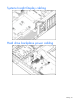
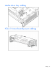
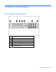

Table Of Contents
- HP ProLiant DL385 Generation 2 Server Maintenance and Service Guide
- Notice
- Contents
- Customer self repair
- Illustrated parts catalog
- Removal and replacement procedures
- Required tools
- Safety considerations
- Preparation procedures
- Access panel
- SAS hard drive blank
- Hot-plug SAS hard drive
- Power supply blank
- Hot-plug power supply
- DC power supply
- Media drive or blank
- Hot-plug fan
- Power supply cage assembly
- Battery-backed write cache procedures
- Air baffle
- Processor fan bracket
- Front bezel
- Systems Insight Display
- Fan board
- Processor fan bracket plate
- Media drive ejector assembly
- PPM
- PPM retainer
- Heatsink
- Processor
- DIMMs
- Power supply backplane
- Hard drive backplane
- Hard drive backplane retainer
- PCI riser cage
- Expansion slot covers
- Expansion slot cover retainer (slots 1 and 2)
- Expansion boards
- Battery
- System board
- I/O fan bracket
- Cabling
- Diagnostic tools
- Component identification
- Front panel components
- Front panel LEDs and buttons
- Rear panel components
- Rear panel LEDs and buttons
- System board
- Systems Insight Display LEDs
- Systems Insight Display LEDs and internal health LED combinations
- Device numbers
- SAS and SATA hard drive LEDs
- SAS and SATA hard drive LED combinations
- PCI riser cage LED
- Battery pack LEDs
- Hot-plug fans (6-fan configuration)
- Hot-plug fans (12-fan configuration)
- Fan board components
- Specifications
- Acronyms and abbreviations
Component identification 89
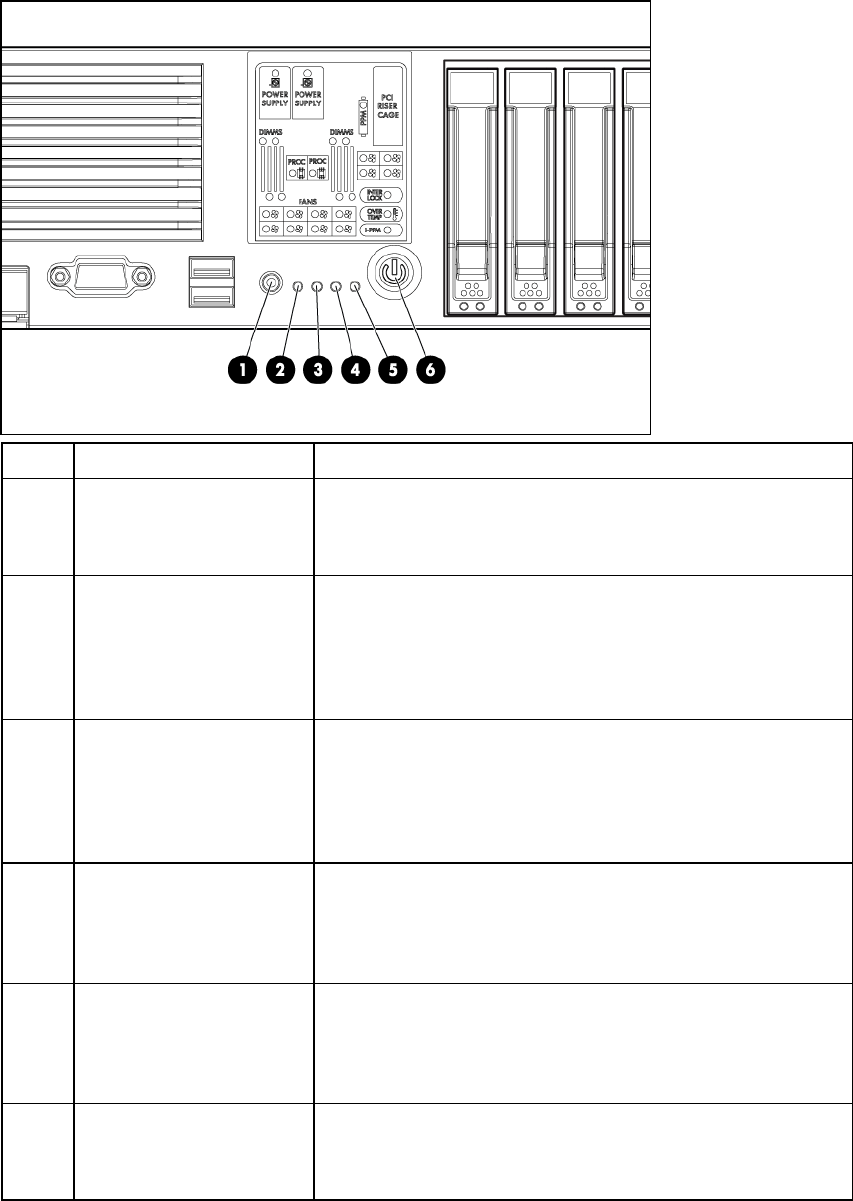
Front panel LEDs and buttons
Item Description Status
1 UID LED button Blue = Activated
Flashing = System being remotely managed
Off = Deactivated
2 Internal health LED Green = Normal
Amber = System degraded. To identify component in degraded
state, refer to Systems Insight Display LEDs.
Red = System critical. To identify component in critical state, refer
to Systems Insight Display LEDs.
3 External health LED (power
supply)
Green = Normal
Amber = Power redundancy failure. To identify component in
degraded state, refer to Systems Insight Display LEDs.
Red = Critical power supply failure. To identify component in
critical state, refer to Systems Insight Display LEDs.
4 NIC 1 link/activity LED Green = Network link
Flashing = Network link and activity
Off = No link to network. If power is off, view the rear panel
RJ45 LEDs for status.
5 NIC 2 link/activity LED Green = Network link
Flashing = Network link and activity
Off = No link to network. If power is off, view the rear panel
RJ45 LEDs for status.
6 Power On/Standby
button/system power LED
Green = System on
Amber = System shut down, but power still applied
Off = Power cord not attached or power supply failure