
HP ProLiant DL385 Generation 2 Server Maintenance and Service Guide
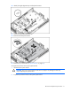
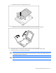
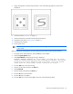

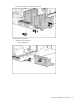
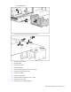
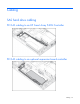
Table Of Contents
- HP ProLiant DL385 Generation 2 Server Maintenance and Service Guide
- Notice
- Contents
- Customer self repair
- Illustrated parts catalog
- Removal and replacement procedures
- Required tools
- Safety considerations
- Preparation procedures
- Access panel
- SAS hard drive blank
- Hot-plug SAS hard drive
- Power supply blank
- Hot-plug power supply
- DC power supply
- Media drive or blank
- Hot-plug fan
- Power supply cage assembly
- Battery-backed write cache procedures
- Air baffle
- Processor fan bracket
- Front bezel
- Systems Insight Display
- Fan board
- Processor fan bracket plate
- Media drive ejector assembly
- PPM
- PPM retainer
- Heatsink
- Processor
- DIMMs
- Power supply backplane
- Hard drive backplane
- Hard drive backplane retainer
- PCI riser cage
- Expansion slot covers
- Expansion slot cover retainer (slots 1 and 2)
- Expansion boards
- Battery
- System board
- I/O fan bracket
- Cabling
- Diagnostic tools
- Component identification
- Front panel components
- Front panel LEDs and buttons
- Rear panel components
- Rear panel LEDs and buttons
- System board
- Systems Insight Display LEDs
- Systems Insight Display LEDs and internal health LED combinations
- Device numbers
- SAS and SATA hard drive LEDs
- SAS and SATA hard drive LED combinations
- PCI riser cage LED
- Battery pack LEDs
- Hot-plug fans (6-fan configuration)
- Hot-plug fans (12-fan configuration)
- Fan board components
- Specifications
- Acronyms and abbreviations
Removal and replacement procedures 74
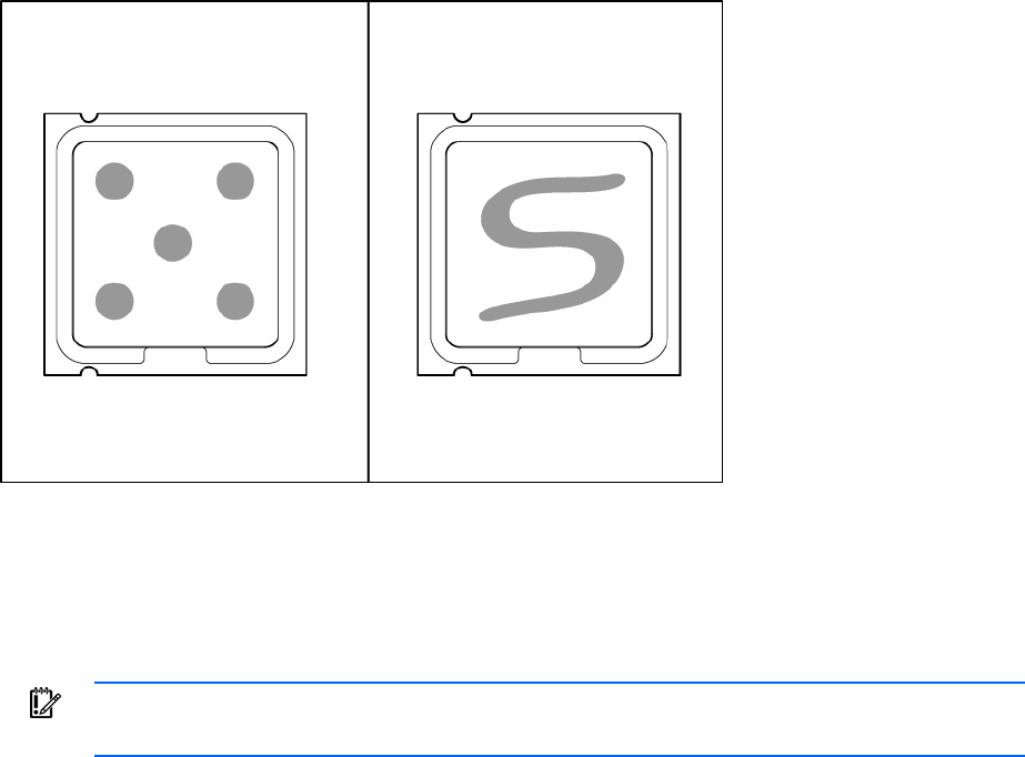
7.
Apply all the grease to the top of the processor in one of the following patterns to ensure even
distribution:
8. Install the heatsink ("Heatsink" on page 50).
9. Install all components removed from the failed system board.
10. Install the access panel ("Access panel" on page 31).
11. Install the power supplies.
12. Power up the server.
IMPORTANT: Install all components with the same configuration that was used on the failed
system board.
After you replace the system board, you must re-enter the server serial number and the product ID.
1. During the server startup sequence, press the F9 key to access RBSU.
2. Select the System Options menu.
3. Select Serial Number. The following warning is displayed:
WARNING! WARNING! WARNING! The serial number is loaded into the system
during the manufacturing process and should NOT be modified. This option
should only be used by qualified service personnel. This value should
always match the serial number sticker located on the chassis.
4. Press the Enter key to clear the warning.
5. Enter the serial number and press the Enter key.
6. Select Product ID.
7. Enter the product ID and press the Enter key.
8. Press the Esc key to close the menu.
9. Press the Esc key to exit RBSU.
10. Press the F10 key to confirm exiting RBSU. The server will automatically reboot.