
HP ProLiant DL385 Generation 2 Server Maintenance and Service Guide
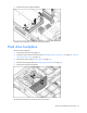
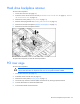

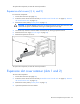
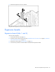
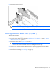
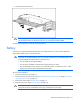
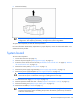

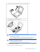
Table Of Contents
- HP ProLiant DL385 Generation 2 Server Maintenance and Service Guide
- Notice
- Contents
- Customer self repair
- Illustrated parts catalog
- Removal and replacement procedures
- Required tools
- Safety considerations
- Preparation procedures
- Access panel
- SAS hard drive blank
- Hot-plug SAS hard drive
- Power supply blank
- Hot-plug power supply
- DC power supply
- Media drive or blank
- Hot-plug fan
- Power supply cage assembly
- Battery-backed write cache procedures
- Air baffle
- Processor fan bracket
- Front bezel
- Systems Insight Display
- Fan board
- Processor fan bracket plate
- Media drive ejector assembly
- PPM
- PPM retainer
- Heatsink
- Processor
- DIMMs
- Power supply backplane
- Hard drive backplane
- Hard drive backplane retainer
- PCI riser cage
- Expansion slot covers
- Expansion slot cover retainer (slots 1 and 2)
- Expansion boards
- Battery
- System board
- I/O fan bracket
- Cabling
- Diagnostic tools
- Component identification
- Front panel components
- Front panel LEDs and buttons
- Rear panel components
- Rear panel LEDs and buttons
- System board
- Systems Insight Display LEDs
- Systems Insight Display LEDs and internal health LED combinations
- Device numbers
- SAS and SATA hard drive LEDs
- SAS and SATA hard drive LED combinations
- PCI riser cage LED
- Battery pack LEDs
- Hot-plug fans (6-fan configuration)
- Hot-plug fans (12-fan configuration)
- Fan board components
- Specifications
- Acronyms and abbreviations
Removal and replacement procedures 63
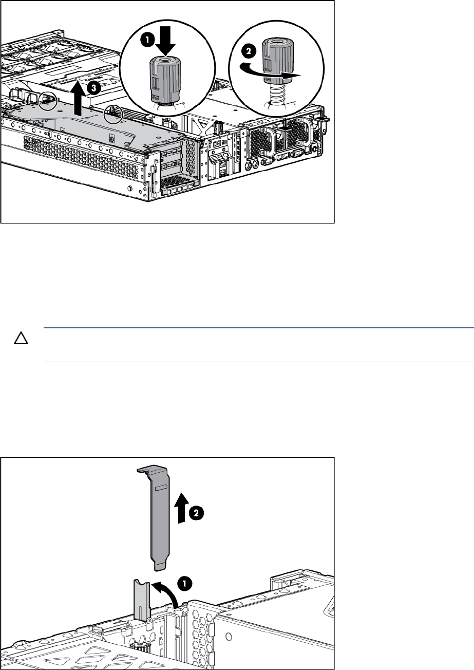
7.
Remove the PCI riser cage.
To replace the component, reverse the removal procedure.
Expansion slot covers
Expansion slot covers (1 and 2)
CAUTION: To prevent improper cooling and thermal damage, do not operate the server unless
all PCI slots have either an expansion slot cover or an expansion board installed.
1. Power down the server (on page 29).
2. Extend or remove the server from the rack ("Extend the server from the rack" on page 28, "Remove
the server from the rack" on page 30).
3. Remove the access panel ("Access panel" on page 31).
4. Remove the expansion slot cover.