
HP ProLiant DL385 Generation 2 Server Maintenance and Service Guide
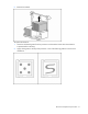
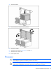
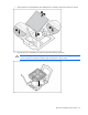
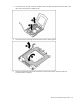
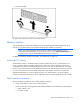
Table Of Contents
- HP ProLiant DL385 Generation 2 Server Maintenance and Service Guide
- Notice
- Contents
- Customer self repair
- Illustrated parts catalog
- Removal and replacement procedures
- Required tools
- Safety considerations
- Preparation procedures
- Access panel
- SAS hard drive blank
- Hot-plug SAS hard drive
- Power supply blank
- Hot-plug power supply
- DC power supply
- Media drive or blank
- Hot-plug fan
- Power supply cage assembly
- Battery-backed write cache procedures
- Air baffle
- Processor fan bracket
- Front bezel
- Systems Insight Display
- Fan board
- Processor fan bracket plate
- Media drive ejector assembly
- PPM
- PPM retainer
- Heatsink
- Processor
- DIMMs
- Power supply backplane
- Hard drive backplane
- Hard drive backplane retainer
- PCI riser cage
- Expansion slot covers
- Expansion slot cover retainer (slots 1 and 2)
- Expansion boards
- Battery
- System board
- I/O fan bracket
- Cabling
- Diagnostic tools
- Component identification
- Front panel components
- Front panel LEDs and buttons
- Rear panel components
- Rear panel LEDs and buttons
- System board
- Systems Insight Display LEDs
- Systems Insight Display LEDs and internal health LED combinations
- Device numbers
- SAS and SATA hard drive LEDs
- SAS and SATA hard drive LED combinations
- PCI riser cage LED
- Battery pack LEDs
- Hot-plug fans (6-fan configuration)
- Hot-plug fans (12-fan configuration)
- Fan board components
- Specifications
- Acronyms and abbreviations
Removal and replacement procedures 60
• Install DIMMs with the same speed.
• Install memory in pairs (banks) beginning with banks farthest away from each populated processor
(banks A and C).
• The server supports multiple memory modes, based on DIMM population. Use RBSU ("HP ROM-
Based Setup Utility" on page 85) to select a mode (System will default to Advanced ECC).
• Observe the following special conditions when installing memory with a second processor:
o Processor 2 can be installed without memory.
o Any memory installed into banks for processor 2 can be used only if processor 2 is installed.
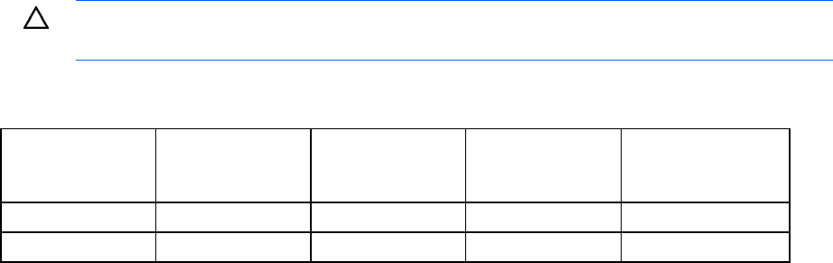
CAUTION: Always wear an antistatic wrist strap when working inside the server.
DIMM population order
Configuration Bank A
1A and 2A
Bank B
3B and 4B
Bank C
5C and 6C
Bank D
7D and 8D
Single processor 1st 2nd — —
Dual processor 1st 3rd 2nd 4th
Power supply backplane
To remove the component:
1. Power down the server (on page 29).
2. Remove all power supplies ("Hot-plug power supply" on page 33).
3. Extend or remove the server from the rack ("Extend the server from the rack" on page 28, "Remove
the server from the rack" on page 30).
4. Remove the access panel ("Access panel" on page 31).
5. Remove the air baffle ("Air baffle" on page 41).