
HP ProLiant DL385 Generation 2 Server Maintenance and Service Guide
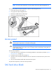
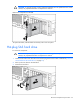

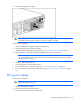

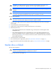
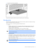

Table Of Contents
- HP ProLiant DL385 Generation 2 Server Maintenance and Service Guide
- Notice
- Contents
- Customer self repair
- Illustrated parts catalog
- Removal and replacement procedures
- Required tools
- Safety considerations
- Preparation procedures
- Access panel
- SAS hard drive blank
- Hot-plug SAS hard drive
- Power supply blank
- Hot-plug power supply
- DC power supply
- Media drive or blank
- Hot-plug fan
- Power supply cage assembly
- Battery-backed write cache procedures
- Air baffle
- Processor fan bracket
- Front bezel
- Systems Insight Display
- Fan board
- Processor fan bracket plate
- Media drive ejector assembly
- PPM
- PPM retainer
- Heatsink
- Processor
- DIMMs
- Power supply backplane
- Hard drive backplane
- Hard drive backplane retainer
- PCI riser cage
- Expansion slot covers
- Expansion slot cover retainer (slots 1 and 2)
- Expansion boards
- Battery
- System board
- I/O fan bracket
- Cabling
- Diagnostic tools
- Component identification
- Front panel components
- Front panel LEDs and buttons
- Rear panel components
- Rear panel LEDs and buttons
- System board
- Systems Insight Display LEDs
- Systems Insight Display LEDs and internal health LED combinations
- Device numbers
- SAS and SATA hard drive LEDs
- SAS and SATA hard drive LED combinations
- PCI riser cage LED
- Battery pack LEDs
- Hot-plug fans (6-fan configuration)
- Hot-plug fans (12-fan configuration)
- Fan board components
- Specifications
- Acronyms and abbreviations
Removal and replacement procedures 39
6.
Remove the power supply cage assembly.
To replace the component, reverse the removal procedure.
Battery-backed write cache procedures
Two types of procedures are provided for the BBWC option:
• Removal and replacement of failed components:
o Removing the cache module (on page 39)
o Removing the battery pack (on page 40)
• Recovery of cached data from a failed server ("Recovering data from the battery-backed write
cache" on page 41)
CAUTION: Do not detach the cable that connects the battery pack to the cache module.
Detaching the cable causes any unsaved data in the cache module to be lost.
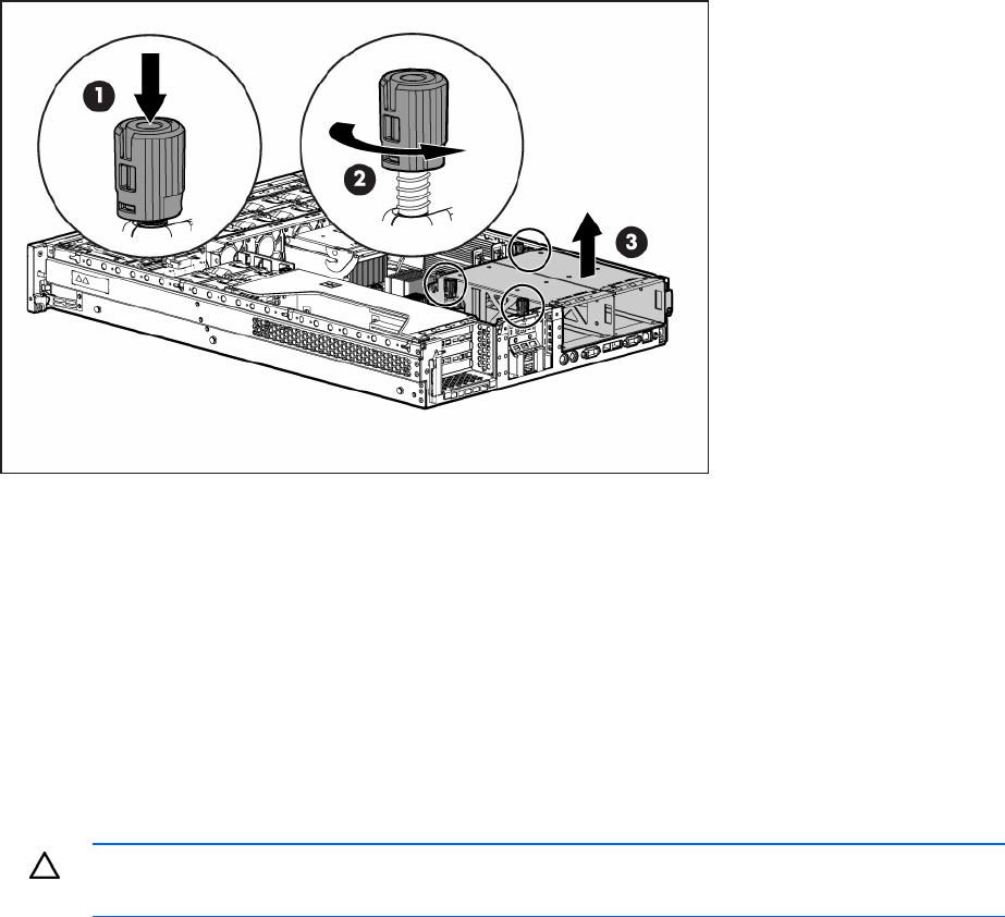
Removing the cache module
To remove the component:
1. Power down the server (on page 29).
2. Extend or remove the server from the rack ("Extend the server from the rack" on page 28, "Remove
the server from the rack" on page 30).
3. Remove the access panel ("Access panel" on page 31).
4. Remove the controller ("Expansion board (slots 1 and 2)" on page 65).