
HP ProLiant DL385 Generation 2 Server Maintenance and Service Guide
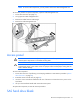
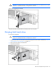

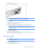

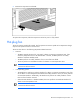

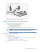
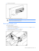
Table Of Contents
- HP ProLiant DL385 Generation 2 Server Maintenance and Service Guide
- Notice
- Contents
- Customer self repair
- Illustrated parts catalog
- Removal and replacement procedures
- Required tools
- Safety considerations
- Preparation procedures
- Access panel
- SAS hard drive blank
- Hot-plug SAS hard drive
- Power supply blank
- Hot-plug power supply
- DC power supply
- Media drive or blank
- Hot-plug fan
- Power supply cage assembly
- Battery-backed write cache procedures
- Air baffle
- Processor fan bracket
- Front bezel
- Systems Insight Display
- Fan board
- Processor fan bracket plate
- Media drive ejector assembly
- PPM
- PPM retainer
- Heatsink
- Processor
- DIMMs
- Power supply backplane
- Hard drive backplane
- Hard drive backplane retainer
- PCI riser cage
- Expansion slot covers
- Expansion slot cover retainer (slots 1 and 2)
- Expansion boards
- Battery
- System board
- I/O fan bracket
- Cabling
- Diagnostic tools
- Component identification
- Front panel components
- Front panel LEDs and buttons
- Rear panel components
- Rear panel LEDs and buttons
- System board
- Systems Insight Display LEDs
- Systems Insight Display LEDs and internal health LED combinations
- Device numbers
- SAS and SATA hard drive LEDs
- SAS and SATA hard drive LED combinations
- PCI riser cage LED
- Battery pack LEDs
- Hot-plug fans (6-fan configuration)
- Hot-plug fans (12-fan configuration)
- Fan board components
- Specifications
- Acronyms and abbreviations
Removal and replacement procedures 36
WARNING: To reduce the risk of injury from electric shock hazards, do not open power
supplies. Refer all maintenance, upgrades, and servicing to qualified personnel.
CAUTION: Do not run the server with one AC power supply and one DC power supply
installed.
CAUTION: Electrostatic discharge (ESD) can damage electronic components. Be sure that you
are properly grounded (earthed) before beginning any installation procedure.
To replace the component:
WARNING: To reduce the risk of electric shock or damage to the equipment, do not connect
the power cord to the power supply until the power supply is installed.
1. Slide the power supply into the power supply bay until the release/lock lever clicks, securing the
power supply.
2. Connect the power cord to the power supply.
3. Tighten the two retaining screws on either side of the power cord connector.
4. Route the power cord:
o If the cable management arm has a left-hand swing, route the power cord through the cable
management arm.
o If the cable management arm has a right-hand swing, remove the cable management arm or
convert it for left-hand swing. For removal instructions, see "Cable management arm with right-
hand swing (on page 30)." For conversion instructions, see the instructions that ship with the 2U
Quick Deploy Rail System.
5. Connect the power cord to the PDU.
6. Be sure that the power supply LED is green ("Rear panel LEDs and buttons" on page 91).
7. Be sure that the front panel external health LED is green ("Front panel LEDs and buttons" on page
89).
Media drive or blank
To remove the component:
CAUTION: To prevent improper cooling and thermal damage, do not operate the server unless
all bays are populated with either a component or a blank.
1. Power down the server (on page 29).