
HP ProLiant DL385 Generation 2 Server Maintenance and Service Guide
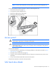


Table Of Contents
- HP ProLiant DL385 Generation 2 Server Maintenance and Service Guide
- Notice
- Contents
- Customer self repair
- Illustrated parts catalog
- Removal and replacement procedures
- Required tools
- Safety considerations
- Preparation procedures
- Access panel
- SAS hard drive blank
- Hot-plug SAS hard drive
- Power supply blank
- Hot-plug power supply
- DC power supply
- Media drive or blank
- Hot-plug fan
- Power supply cage assembly
- Battery-backed write cache procedures
- Air baffle
- Processor fan bracket
- Front bezel
- Systems Insight Display
- Fan board
- Processor fan bracket plate
- Media drive ejector assembly
- PPM
- PPM retainer
- Heatsink
- Processor
- DIMMs
- Power supply backplane
- Hard drive backplane
- Hard drive backplane retainer
- PCI riser cage
- Expansion slot covers
- Expansion slot cover retainer (slots 1 and 2)
- Expansion boards
- Battery
- System board
- I/O fan bracket
- Cabling
- Diagnostic tools
- Component identification
- Front panel components
- Front panel LEDs and buttons
- Rear panel components
- Rear panel LEDs and buttons
- System board
- Systems Insight Display LEDs
- Systems Insight Display LEDs and internal health LED combinations
- Device numbers
- SAS and SATA hard drive LEDs
- SAS and SATA hard drive LED combinations
- PCI riser cage LED
- Battery pack LEDs
- Hot-plug fans (6-fan configuration)
- Hot-plug fans (12-fan configuration)
- Fan board components
- Specifications
- Acronyms and abbreviations
Removal and replacement procedures 35
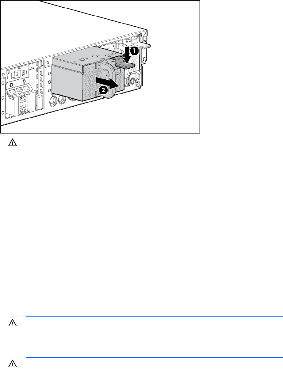
4.
Loosen the two thumbscrews on either side of the power cord.
5. Disconnect the power cord from the power supply.
6. Remove the power supply.
WARNING: To reduce the risk of electric shock, fire, and damage to the equipment, this
product must be installed in accordance with the following guidelines:
• This power supply is intended only for installation in HP servers located in a restricted
access location.
• This power supply is not intended for direct connection to the DC supply branch circuit. It
should only be connected to a power distribution unit (PDU) that provides an independent
overcurrent-protected output for each DC power supply. Each output overcurrent-protected
device in the PDU must be suitable for interrupting fault current available from the DC
power source and must be rated no more than 50A.
• This power supply is designed to be connected only to a DC power source that can be
classified as SELV or TNV, in accordance with applicable national requirements for
Information Technology Equipment and Telecommunications Equipment. Generally, these
requirements are based on the International Standard for Information Technology
Equipment, IEC 60950, and/or the European Telecommunication Standard ETS 300 132-
2. The DC source is to have one pole (Neutral/Return) reliably connected to earth ground
in accordance with local/regional electric codes and/or regulations.
• The green/yellow lead of the power cable assembly must be connected to a suitable
ground/earth terminal. This terminal must be connected to a suitable building ground/earth
terminal in accordance with local/regional electric codes/regulations. Do not rely on the
rack or cabinet chassis to provide adequate ground/earth continuity.
WARNING: To reduce the risk of personal injury or damage to the equipment, the installation
of power supplies should be performed only by individuals who are qualified in servicing
server equipment and trained to deal with products capable of producing hazardous energy
levels.
WARNING: To reduce the risk of personal injury from hot surfaces, observe the thermal labels
on each power supply or module.