
HP ProLiant DL385 Generation 2 Server Maintenance and Service Guide
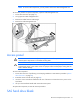
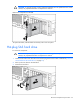

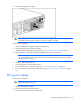


Table Of Contents
- HP ProLiant DL385 Generation 2 Server Maintenance and Service Guide
- Notice
- Contents
- Customer self repair
- Illustrated parts catalog
- Removal and replacement procedures
- Required tools
- Safety considerations
- Preparation procedures
- Access panel
- SAS hard drive blank
- Hot-plug SAS hard drive
- Power supply blank
- Hot-plug power supply
- DC power supply
- Media drive or blank
- Hot-plug fan
- Power supply cage assembly
- Battery-backed write cache procedures
- Air baffle
- Processor fan bracket
- Front bezel
- Systems Insight Display
- Fan board
- Processor fan bracket plate
- Media drive ejector assembly
- PPM
- PPM retainer
- Heatsink
- Processor
- DIMMs
- Power supply backplane
- Hard drive backplane
- Hard drive backplane retainer
- PCI riser cage
- Expansion slot covers
- Expansion slot cover retainer (slots 1 and 2)
- Expansion boards
- Battery
- System board
- I/O fan bracket
- Cabling
- Diagnostic tools
- Component identification
- Front panel components
- Front panel LEDs and buttons
- Rear panel components
- Rear panel LEDs and buttons
- System board
- Systems Insight Display LEDs
- Systems Insight Display LEDs and internal health LED combinations
- Device numbers
- SAS and SATA hard drive LEDs
- SAS and SATA hard drive LED combinations
- PCI riser cage LED
- Battery pack LEDs
- Hot-plug fans (6-fan configuration)
- Hot-plug fans (12-fan configuration)
- Fan board components
- Specifications
- Acronyms and abbreviations
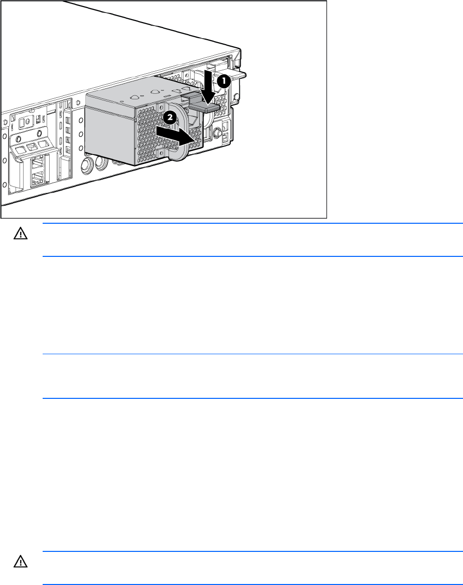
Removal and replacement procedures 34
3.
Remove the hot-plug power supply.
WARNING: To reduce the risk of electric shock or damage to the equipment, do not connect
the power cord to the power supply until the power supply is installed.
To replace the component:
1. Slide the hot-plug power supply into the power supply bay.
2. Connect the power cord to the power supply.
3. Install the cable management arm, if removed ("Access the product rear panel" on page 30).
4. Route the power cord through the cable management arm or power cord anchor.
NOTE: If using the power cord anchor, be sure to leave enough slack in the power cord so
that the redundant power supply can be removed without disconnecting the power cord from
the primary power supply.
5. Close the cable management arm.
6. Connect the power cord to the power source.
7. Be sure that the power supply LED is green ("Rear panel LEDs and buttons" on page 91).
8. Be sure that the front panel external health LED is green ("Front panel LEDs and buttons" on page
89).
DC power supply
To remove the component:
WARNING: To reduce the risk of personal injury, remove all power from the DC source before
disconnecting the power cord.
1. Identify the failed power supply.
2. Disconnect the power cord from the PDU.
3. Remove the power cord from the retaining clip.