
HP ProLiant DL385 Generation 2 Server Maintenance and Service Guide
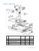
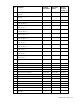
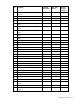
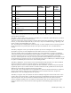
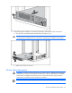
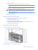
Table Of Contents
- HP ProLiant DL385 Generation 2 Server Maintenance and Service Guide
- Notice
- Contents
- Customer self repair
- Illustrated parts catalog
- Removal and replacement procedures
- Required tools
- Safety considerations
- Preparation procedures
- Access panel
- SAS hard drive blank
- Hot-plug SAS hard drive
- Power supply blank
- Hot-plug power supply
- DC power supply
- Media drive or blank
- Hot-plug fan
- Power supply cage assembly
- Battery-backed write cache procedures
- Air baffle
- Processor fan bracket
- Front bezel
- Systems Insight Display
- Fan board
- Processor fan bracket plate
- Media drive ejector assembly
- PPM
- PPM retainer
- Heatsink
- Processor
- DIMMs
- Power supply backplane
- Hard drive backplane
- Hard drive backplane retainer
- PCI riser cage
- Expansion slot covers
- Expansion slot cover retainer (slots 1 and 2)
- Expansion boards
- Battery
- System board
- I/O fan bracket
- Cabling
- Diagnostic tools
- Component identification
- Front panel components
- Front panel LEDs and buttons
- Rear panel components
- Rear panel LEDs and buttons
- System board
- Systems Insight Display LEDs
- Systems Insight Display LEDs and internal health LED combinations
- Device numbers
- SAS and SATA hard drive LEDs
- SAS and SATA hard drive LED combinations
- PCI riser cage LED
- Battery pack LEDs
- Hot-plug fans (6-fan configuration)
- Hot-plug fans (12-fan configuration)
- Fan board components
- Specifications
- Acronyms and abbreviations
Removal and replacement procedures 30
1.
Back up the server data.
2. Shut down the operating system as directed by the operating system documentation.
NOTE: If the operating system automatically places the server in Standby mode, omit the next
step.
3. Press the Power On/Standby button to place the server in Standby mode. When the server activates
Standby power mode, the system power LED changes to amber.
IMPORTANT: Pressing the UID button illuminates the blue UID LEDs on the front and rear
panels. In a rack environment, this feature facilitates locating a server when moving between
the front and rear of the rack.
4. Disconnect the power cords.
The system is now without power.
Remove the server from the rack
To remove the server from an HP, Compaq branded, telco, or third-party rack:
1. Power down the server (on page 29).
2. Extend the server from the rack (on page 28).
3. Disconnect the cabling and remove the server from the rack. For more information, refer to the
documentation that ships with the rack mounting option.
4. Place the server on a sturdy, level surface.
Access the product rear panel
Cable management arm with left-hand swing
To access the server rear panel, open the cable management arm.
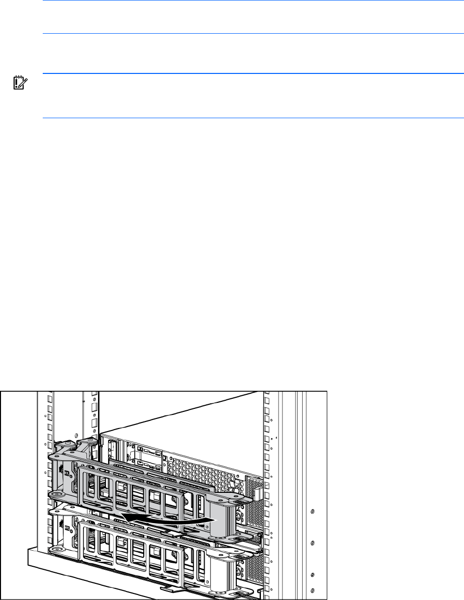
Cable management arm with right-hand swing