
HP ProLiant DL385 Generation 2 Server Maintenance and Service Guide
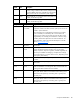
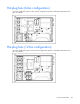
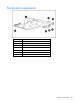
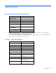
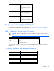
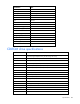
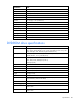
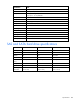
Table Of Contents
- HP ProLiant DL385 Generation 2 Server Maintenance and Service Guide
- Notice
- Contents
- Customer self repair
- Illustrated parts catalog
- Removal and replacement procedures
- Required tools
- Safety considerations
- Preparation procedures
- Access panel
- SAS hard drive blank
- Hot-plug SAS hard drive
- Power supply blank
- Hot-plug power supply
- DC power supply
- Media drive or blank
- Hot-plug fan
- Power supply cage assembly
- Battery-backed write cache procedures
- Air baffle
- Processor fan bracket
- Front bezel
- Systems Insight Display
- Fan board
- Processor fan bracket plate
- Media drive ejector assembly
- PPM
- PPM retainer
- Heatsink
- Processor
- DIMMs
- Power supply backplane
- Hard drive backplane
- Hard drive backplane retainer
- PCI riser cage
- Expansion slot covers
- Expansion slot cover retainer (slots 1 and 2)
- Expansion boards
- Battery
- System board
- I/O fan bracket
- Cabling
- Diagnostic tools
- Component identification
- Front panel components
- Front panel LEDs and buttons
- Rear panel components
- Rear panel LEDs and buttons
- System board
- Systems Insight Display LEDs
- Systems Insight Display LEDs and internal health LED combinations
- Device numbers
- SAS and SATA hard drive LEDs
- SAS and SATA hard drive LED combinations
- PCI riser cage LED
- Battery pack LEDs
- Hot-plug fans (6-fan configuration)
- Hot-plug fans (12-fan configuration)
- Fan board components
- Specifications
- Acronyms and abbreviations

Component identification 101
Item ID Color Description
2 Green Auxiliary Power LED. This LED glows steadily when 3.3V
auxiliary voltage is detected. The auxiliary voltage is used
to preserve BBWC data and is available any time that the
system power cords are connected to a power supply.
3 Amber Battery Health LED. To interpret the illumination patterns of
this LED, see the following table.
4 Green BBWC Status LED. To interpret the illumination patterns of
this LED, see the following table.
LED3 pattern LED4 pattern Interpretation
— One blink every
two seconds
The system is powered down, and the cache contains data that has
not yet been written to the drives. Restore system power as soon as
possible to prevent data loss.
Data preservation time is extended any time that 3.3 V auxiliary
power is available, as indicated by LED 2. In the absence of
auxiliary power, battery power alone preserves the data. A fully-
charged battery can normally preserve data for at least two days.
The battery lifetime also depends on the cache module size. For
further information, refer to the controller QuickSpecs on the HP
website (http://www.hp.com
).
— Double blink,
then pause
The cache microcontroller is waiting for the host controller to
communicate.
— One blink per
second
The battery pack is below the minimum charge level and is being
charged. Features that require a battery (such as write cache,
capacity expansion, stripe size migration, and RAID migration) are
temporarily unavailable until charging is complete. The recharge
process takes between 15 minutes and two hours, depending on the
initial capacity of the battery.
— Steady glow The battery pack is fully charged, and posted write data is stored in
the cache.
— Off The battery pack is fully charged, and there is no posted write data
in the cache.
One blink per
second
One blink per
second
An alternating green and amber blink pattern indicates that the
cache microcontroller is executing from within its boot loader and
receiving new flash code from the host controller.
Steady glow — There is a short circuit across the battery terminals or within the
battery pack. BBWC features are disabled until the battery pack is
replaced. The life expectancy of a battery pack is typically more
than three years.
One blink per
second
— There is an open circuit across the battery terminals or within the
battery pack. BBWC features are disabled until the battery pack is
replaced. The life expectancy of a battery pack is typically more
than three years.