
HP StorageWorks 4400 Scalable NAS File Services wiring diagrams (AN595-96002, September 2008)
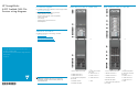

KVM wiring
1. TFT/Keyboard is mounted in front of the KVM switch
2. DL320 G5p
KVM Connection
3. DL380G5KVMConnections
System
KVM por t
DL320G5CVS
erver
1
DL380G5Server1(Bottom) 2
DL380G5Server2 3
DL380G5Server3
4
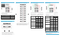
Minimum EVA4400 configuration
1.
Cable connects controller 1, device port 1B (top left — Cntrl 1,
DP1B) to I/O module B, port 2 (bottom right -I/O B, P2).
2.
Cable connects controller 2, device port 1A (top right — Cntrl 2,
DP1A) to I/O module A, port 2 (bottom left -I/O A, P2)
Maximum EVA4400
configuration
1.
Cableconnectscontroller1,deviceport1B(topleft—Cntrl1,
DP1B) to I/O module B, port 2 (bottom right -I/O B, P2).
2.
Cable connects controller 2, device p ort 1A (top right — Cntrl 2,
DP1A) to I/O module A, po rt 2 (bottom left -I/O A, P2)
Fibre Channel wi
ring
1. D L 32 0 G5 p Ri g h t F C H BA
port
4. DL320 G5p Left FC HBA port
2.DL380G5LeftFCHBAport
5.DL380G5R
ight FC HBA port
3. All to top A8000A SAN
Switch
6. All to bottom A8000A SAN
Switch
System System FC
port
A8000A
SAN
Switch 1
A8000A
SAN
Switch 2
Left
1
DL380G5S
erver 1
(Bottom)
Right
1
Left
2
DL380G5Server2
Right
2
Left
3
DL380G5Server3
Right
3
Left
5
DL320 G5 CV Server
Right
5
1
0
EVA Controller Left
20
1
4
EVA Controller Right
2
4
Ethernet wiring
1. DL320 G5p Embedded NIC1 port
4. DL320 G5p iLO2
port
2. DL380 G5 N
IC1 ports
5. DL380G5iLO2
ports
3. EV A4400 TBM
ProCurve
System
System NIC
port
VLAN 1
VLAN 2
Embedded
NIC 1
Port 1
DL380 G5 Server 1
(Bottom)
iLO 2 Port 9
Embedded
NIC 1
Port 2
DL380 G5 Server 2
iLO 2 Port 10
Embedded
NIC 1
Port 3
DL380 G5 Server 3
iLO 2
Port 11
Embedded
NIC 1
Port 4
Embedded
NIC 2
Port 1 9
DL320G5CVServer
iLO2 Port 12
EVA TBM
Admin P ort
Port 6
A8000A SAN Switch
1
Admin P ort
Port 7
A8000A SAN Switch
2
Admin P ort
Port 8
NOTE:
The ProCurve 2824 is split into 2 VLANs—VLAN 1 and VLAN
2. VLAN 1 is comprised of switch ports 1-8. VLA N 2 is
comprised of switch ports 9-24.