
HP ProLiant DL380 G6 Server User Guide
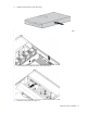
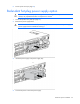
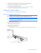
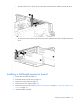
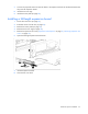
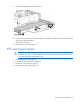
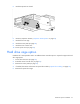
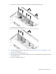
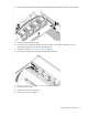
Table Of Contents
- HP ProLiant DL380 G6 Server User Guide
- Abstract
- Notice
- Contents
- Component identification
- Front panel components
- Front panel LEDs and buttons
- Systems Insight Display LEDs
- Systems Insight Display LED combinations
- Rear panel components
- Rear panel LEDs and buttons
- Non-hot-plug PCI riser board slot definitions
- System board components
- SAS and SATA device numbers
- SAS and SATA hard drive LEDs
- SAS and SATA hard drive LED combinations
- PCI riser cage LEDs
- Battery pack LEDs
- Hot-plug fans
- Operations
- Setup
- Hardware options installation
- Introduction
- Processor option
- Memory options
- Hot-plug SAS hard drive options
- Optical drive option
- Redundant hot-plug power supply option
- Expansion board options
- PCI riser board option
- Hard drive cage option
- HP Trusted Platform Module option
- Cabling
- Configuration and utilities
- Troubleshooting
- Battery replacement
- Regulatory compliance notices
- Regulatory compliance identification numbers
- Federal Communications Commission notice
- Declaration of conformity for products marked with the FCC logo, United States only
- Modifications
- Cables
- Canadian notice (Avis Canadien)
- European Union regulatory notice
- Disposal of waste equipment by users in private households in the European Union
- Japanese notice
- BSMI notice
- Korean notice
- Chinese notice
- Laser compliance
- Battery replacement notice
- Taiwan battery recycling notice
- Power cord statement for Japan
- Electrostatic discharge
- Specifications
- Technical support
- Acronyms and abbreviations
- Index
Hardware options installation 53
5.
Route the power cord through the power cord anchor or cable management arm.
6. Reposition the cable management arm into the operating position.
7. Connect the power cord to the power source.
8. Be sure that the power supply LED is green ("Rear panel LEDs and buttons" on page 12).
9. Verify that the corresponding power supply LED on the SID is green.
Expansion board options
The server supports PCI, PCI-X, and PCI Express expansion boards.
Removing expansion slot covers
CAUTION: To prevent damage to the server or expansion boards, power down the server and
remove all AC power cords before removing or installing the PCI riser cage.
CAUTION: For proper cooling do not operate the server without the access panel, baffles,
expansion slot covers, or blanks installed. If the server supports hot-plug components, minimize
the amount of time the access panel is open.
1. Power down the server (on page 22).
2. Extend the server from the rack (on page 22).
3. Remove the access panel (on page 23).
4. Remove the PCI riser cage (on page 26).
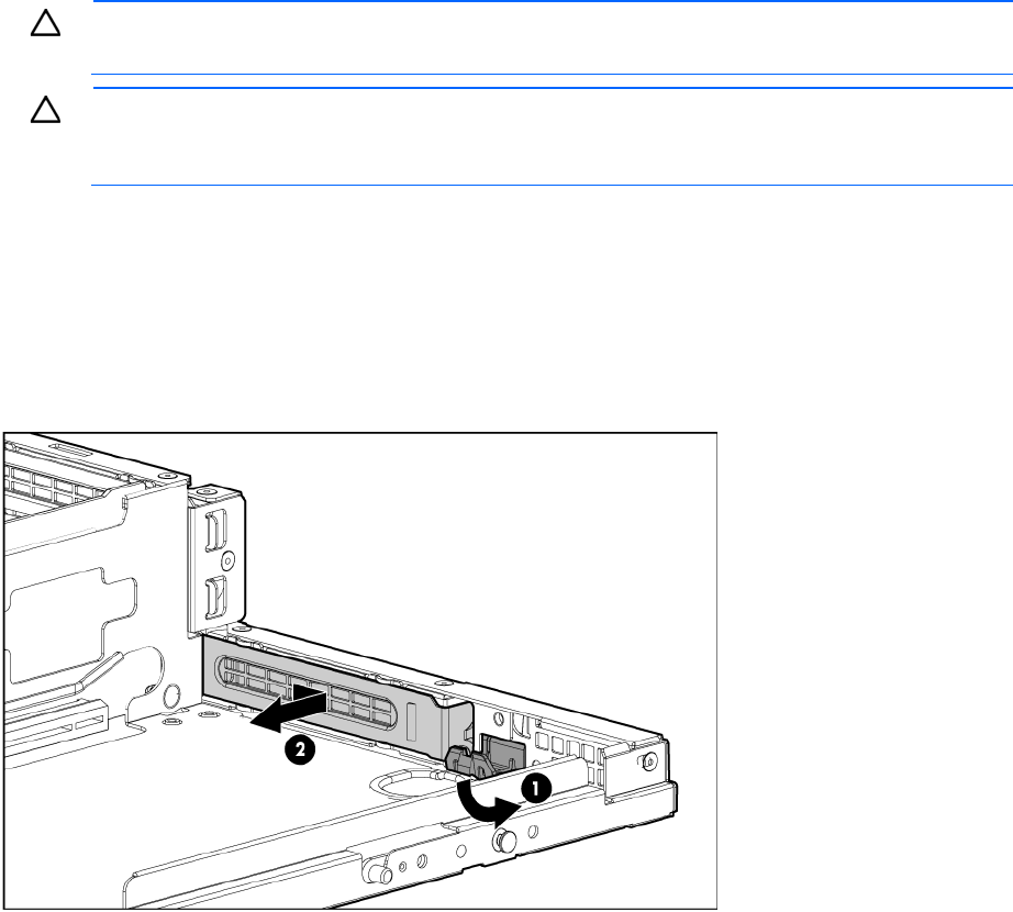
5. Remove the expansion slot cover:
o To remove slot cover 1 or 4, push in on the retainer to release it, and then slide out the cover.