
HP ProLiant DL380 G6 Server User Guide
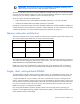
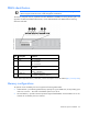
Table Of Contents
- HP ProLiant DL380 G6 Server User Guide
- Abstract
- Notice
- Contents
- Component identification
- Front panel components
- Front panel LEDs and buttons
- Systems Insight Display LEDs
- Systems Insight Display LED combinations
- Rear panel components
- Rear panel LEDs and buttons
- Non-hot-plug PCI riser board slot definitions
- System board components
- SAS and SATA device numbers
- SAS and SATA hard drive LEDs
- SAS and SATA hard drive LED combinations
- PCI riser cage LEDs
- Battery pack LEDs
- Hot-plug fans
- Operations
- Setup
- Hardware options installation
- Introduction
- Processor option
- Memory options
- Hot-plug SAS hard drive options
- Optical drive option
- Redundant hot-plug power supply option
- Expansion board options
- PCI riser board option
- Hard drive cage option
- HP Trusted Platform Module option
- Cabling
- Configuration and utilities
- Troubleshooting
- Battery replacement
- Regulatory compliance notices
- Regulatory compliance identification numbers
- Federal Communications Commission notice
- Declaration of conformity for products marked with the FCC logo, United States only
- Modifications
- Cables
- Canadian notice (Avis Canadien)
- European Union regulatory notice
- Disposal of waste equipment by users in private households in the European Union
- Japanese notice
- BSMI notice
- Korean notice
- Chinese notice
- Laser compliance
- Battery replacement notice
- Taiwan battery recycling notice
- Power cord statement for Japan
- Electrostatic discharge
- Specifications
- Technical support
- Acronyms and abbreviations
- Index
Hardware options installation 46
Mirrored Memory population guidelines
For Mirrored Memory mode configurations, observe the following guidelines:
• Observe the general DIMM slot population guidelines (on page 45).
• Always install DIMMs in channels 1 and 2 for each installed processor.
• Do not install DIMMs in channel 3 for any processor.
• DIMMs installed on channel 1 and channel 2 of an installed processor must be identical.
• In multi-processor configurations, each processor must have a valid Mirrored Memory configuration.
• In multi-processor configurations, each processor may have a different valid Mirrored Memory
configuration.
Single-processor Mirrored Memory population order
For Mirrored Memory mode configurations with a single processor, populate the DIMM slots in the following
order:
• RDIMM
o First: A and B
o Next: D and E
o Last: G and H
o Do not populate slots C, F, or I.
• UDIMM
o First: A and B
o Last: D and E
o Do not populate slots C, F, G, H, or I.
After installing the DIMMs, use RBSU to configure the system for Mirrored Memory support ("Configuring
mirrored memory" on page 67).
Multi-processor Mirrored Memory population order
For Mirrored Memory mode configurations with multiple processors, populate the DIMM slots for each
processor in the following order:
• RDIMM
o First: A and B
o Next: D and E
o Last: G and H
o Do not populate slots C, F, or I.
• UDIMM
o First: A and B
o Last: D and E
o Do not populate slots C, F, G, H, or I.
After installing the DIMMs, use RBSU to configure the system for mirrored memory support ("Configuring
mirrored memory" on page 67).