
HP ProLiant DL380 G6 Server User Guide
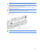
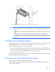
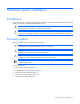
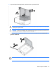
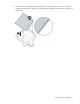
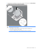
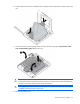
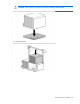
Table Of Contents
- HP ProLiant DL380 G6 Server User Guide
- Abstract
- Notice
- Contents
- Component identification
- Front panel components
- Front panel LEDs and buttons
- Systems Insight Display LEDs
- Systems Insight Display LED combinations
- Rear panel components
- Rear panel LEDs and buttons
- Non-hot-plug PCI riser board slot definitions
- System board components
- SAS and SATA device numbers
- SAS and SATA hard drive LEDs
- SAS and SATA hard drive LED combinations
- PCI riser cage LEDs
- Battery pack LEDs
- Hot-plug fans
- Operations
- Setup
- Hardware options installation
- Introduction
- Processor option
- Memory options
- Hot-plug SAS hard drive options
- Optical drive option
- Redundant hot-plug power supply option
- Expansion board options
- PCI riser board option
- Hard drive cage option
- HP Trusted Platform Module option
- Cabling
- Configuration and utilities
- Troubleshooting
- Battery replacement
- Regulatory compliance notices
- Regulatory compliance identification numbers
- Federal Communications Commission notice
- Declaration of conformity for products marked with the FCC logo, United States only
- Modifications
- Cables
- Canadian notice (Avis Canadien)
- European Union regulatory notice
- Disposal of waste equipment by users in private households in the European Union
- Japanese notice
- BSMI notice
- Korean notice
- Chinese notice
- Laser compliance
- Battery replacement notice
- Taiwan battery recycling notice
- Power cord statement for Japan
- Electrostatic discharge
- Specifications
- Technical support
- Acronyms and abbreviations
- Index
Setup 32
CAUTION: Always plan the rack installation so that the heaviest item is on the bottom of the rack.
Install the heaviest item first, and continue to populate the rack from the bottom to the top.
1. Install the server and cable management arm into the rack. For more information, see the installation
instructions that ship with the 2U Quick Deploy Rail System.
2. Connect peripheral devices to the server.For connector identification information, see Rear panel
components (on page 11) in this guide.
WARNING: To reduce the risk of electric shock, fire, or damage to the equipment, do not plug
telephone or telecommunications connectors into RJ-45 connectors.
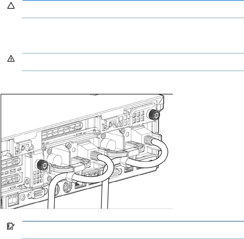
3. Connect the power cord to the rear of the server.
4. Install power cord anchors.
5. Secure cables to the cable management arm.
IMPORTANT:
When using cable management arm components, be sure to leave enough slack
in each of the cables to prevent damage to the cables when the server is extended from the rack.