
HP ProLiant DL380 G6 Server User Guide
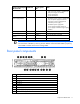
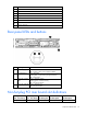
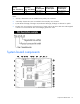
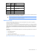
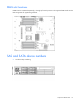
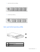
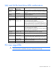
Table Of Contents
- HP ProLiant DL380 G6 Server User Guide
- Abstract
- Notice
- Contents
- Component identification
- Front panel components
- Front panel LEDs and buttons
- Systems Insight Display LEDs
- Systems Insight Display LED combinations
- Rear panel components
- Rear panel LEDs and buttons
- Non-hot-plug PCI riser board slot definitions
- System board components
- SAS and SATA device numbers
- SAS and SATA hard drive LEDs
- SAS and SATA hard drive LED combinations
- PCI riser cage LEDs
- Battery pack LEDs
- Hot-plug fans
- Operations
- Setup
- Hardware options installation
- Introduction
- Processor option
- Memory options
- Hot-plug SAS hard drive options
- Optical drive option
- Redundant hot-plug power supply option
- Expansion board options
- PCI riser board option
- Hard drive cage option
- HP Trusted Platform Module option
- Cabling
- Configuration and utilities
- Troubleshooting
- Battery replacement
- Regulatory compliance notices
- Regulatory compliance identification numbers
- Federal Communications Commission notice
- Declaration of conformity for products marked with the FCC logo, United States only
- Modifications
- Cables
- Canadian notice (Avis Canadien)
- European Union regulatory notice
- Disposal of waste equipment by users in private households in the European Union
- Japanese notice
- BSMI notice
- Korean notice
- Chinese notice
- Laser compliance
- Battery replacement notice
- Taiwan battery recycling notice
- Power cord statement for Japan
- Electrostatic discharge
- Specifications
- Technical support
- Acronyms and abbreviations
- Index
Component identification 15
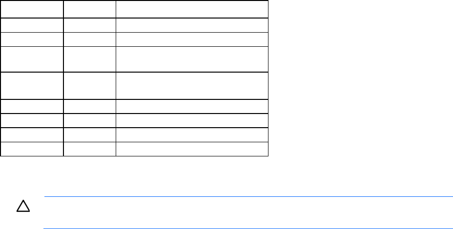
Position Default Function
S3
Off Reserved
S4
Off Reserved
S5
Off Off = Power-on password is enabled.
On = Power-on password is disabled.
S6
Off Off = No function
On = Clear NVRAM
S7
— Reserved
S8
— Reserved
S9
— Reserved
S10
— Reserved
When the system maintenance switch position 6 is set to the On position, the system is prepared to erase all
system configuration settings from both CMOS and NVRAM.
CAUTION: Clearing CMOS and/or NVRAM deletes configuration information. Be sure to
properly configure the server or data loss could occur.
NMI functionality
An NMI crash dump enables administrators to create crash dump files when a system is hung and not
responding to traditional debug mechanisms.
Crash dump log analysis is an essential part of diagnosing reliability problems, such as hangs in operating
systems, device drivers, and applications. Many crashes freeze a system, and the only available action for
administrators is to cycle the system power. Resetting the system erases any information that could support
problem analysis, but the NMI feature preserves that information by performing a memory dump before a
hard reset.
To force the OS to invoke the NMI handler and generate a crash dump log, the administrator can do any of
the following:
• Short the NMI jumper pins
• Press the NMI switch
• Use the iLO Virtual NMI feature
For additional information, see the whitepaper on the HP website
(http://h20000.www2.hp.com/bc/docs/support/SupportManual/c00797875/c00797875.pdf).