
HP ProLiant DL380 G6 Server User Guide
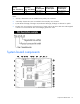
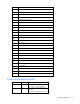
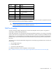
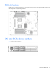
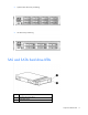
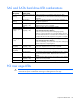
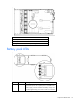
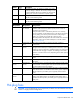
Table Of Contents
- HP ProLiant DL380 G6 Server User Guide
- Abstract
- Notice
- Contents
- Component identification
- Front panel components
- Front panel LEDs and buttons
- Systems Insight Display LEDs
- Systems Insight Display LED combinations
- Rear panel components
- Rear panel LEDs and buttons
- Non-hot-plug PCI riser board slot definitions
- System board components
- SAS and SATA device numbers
- SAS and SATA hard drive LEDs
- SAS and SATA hard drive LED combinations
- PCI riser cage LEDs
- Battery pack LEDs
- Hot-plug fans
- Operations
- Setup
- Hardware options installation
- Introduction
- Processor option
- Memory options
- Hot-plug SAS hard drive options
- Optical drive option
- Redundant hot-plug power supply option
- Expansion board options
- PCI riser board option
- Hard drive cage option
- HP Trusted Platform Module option
- Cabling
- Configuration and utilities
- Troubleshooting
- Battery replacement
- Regulatory compliance notices
- Regulatory compliance identification numbers
- Federal Communications Commission notice
- Declaration of conformity for products marked with the FCC logo, United States only
- Modifications
- Cables
- Canadian notice (Avis Canadien)
- European Union regulatory notice
- Disposal of waste equipment by users in private households in the European Union
- Japanese notice
- BSMI notice
- Korean notice
- Chinese notice
- Laser compliance
- Battery replacement notice
- Taiwan battery recycling notice
- Power cord statement for Japan
- Electrostatic discharge
- Specifications
- Technical support
- Acronyms and abbreviations
- Index
Component identification 14
Item Description
1
Processor 2 DIMM slots
2
SAS power connector A
3
SAS power connector B
4
Front I/O connector
5
SATA optical drive connector
6
Internal USB connector
7
System battery
8
Power supply backplane connector
9
NMI jumper
10
System maintenance switch
11
Processor socket 2
12
Primary riser connector
13
SD card slot
14
TPM connector
15
Processor socket 1 (populated)
16
Processor 1 DIMM slots
17
Secondary riser connector
18
SAS connector A
19
SAS connector B
20
Cache module connector
21
Fan connector 1
22
Fan connector 2
23
Fan connector 3
24
Fan connector 4
25
Fan connector 5
26
Fan connector 6
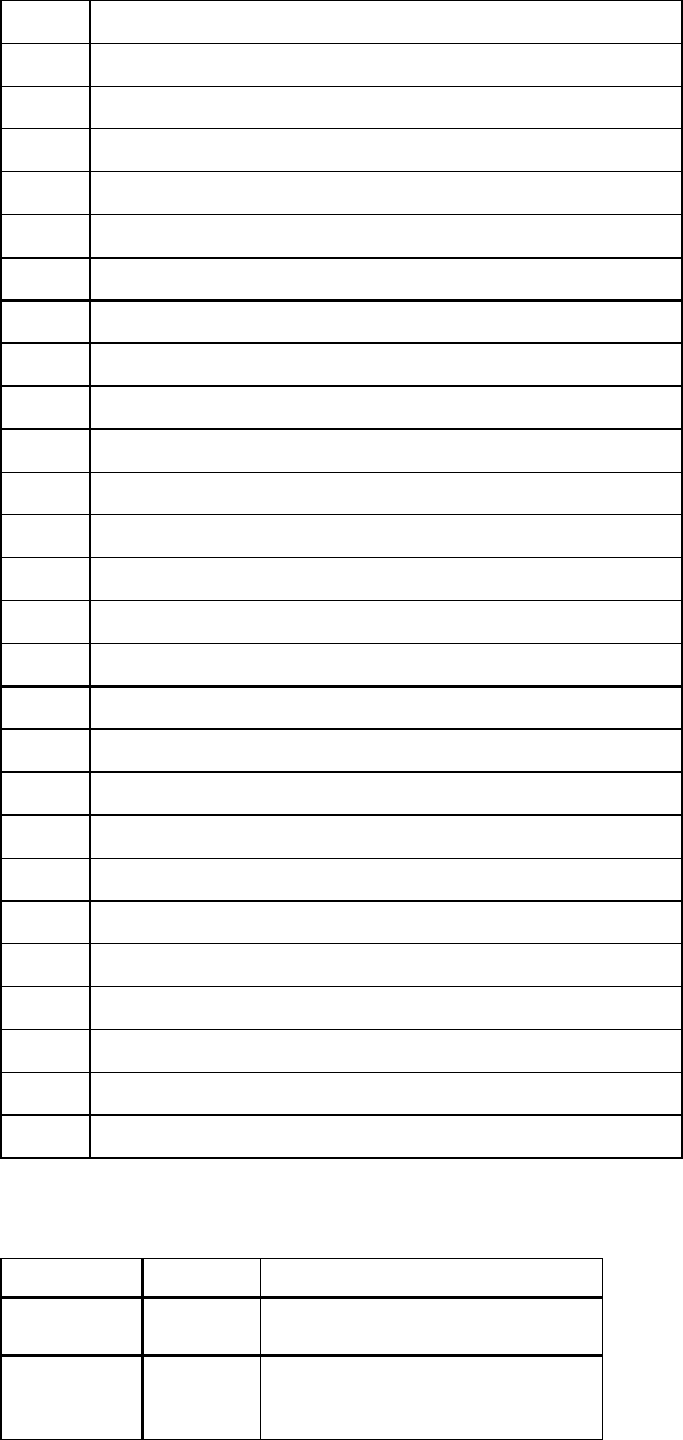
System maintenance switch
Position Default Function
S1
Off Off = iLO 2 security is enabled.
On = iLO 2 security is disabled.
S2
Off Off = System configuration can be
changed.
On = System configuration is locked.