
HP ProLiant DL380 G6 Server User Guide

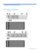
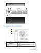
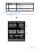
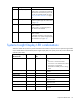
Table Of Contents
- HP ProLiant DL380 G6 Server User Guide
- Abstract
- Notice
- Contents
- Component identification
- Front panel components
- Front panel LEDs and buttons
- Systems Insight Display LEDs
- Systems Insight Display LED combinations
- Rear panel components
- Rear panel LEDs and buttons
- Non-hot-plug PCI riser board slot definitions
- System board components
- SAS and SATA device numbers
- SAS and SATA hard drive LEDs
- SAS and SATA hard drive LED combinations
- PCI riser cage LEDs
- Battery pack LEDs
- Hot-plug fans
- Operations
- Setup
- Hardware options installation
- Introduction
- Processor option
- Memory options
- Hot-plug SAS hard drive options
- Optical drive option
- Redundant hot-plug power supply option
- Expansion board options
- PCI riser board option
- Hard drive cage option
- HP Trusted Platform Module option
- Cabling
- Configuration and utilities
- Troubleshooting
- Battery replacement
- Regulatory compliance notices
- Regulatory compliance identification numbers
- Federal Communications Commission notice
- Declaration of conformity for products marked with the FCC logo, United States only
- Modifications
- Cables
- Canadian notice (Avis Canadien)
- European Union regulatory notice
- Disposal of waste equipment by users in private households in the European Union
- Japanese notice
- BSMI notice
- Korean notice
- Chinese notice
- Laser compliance
- Battery replacement notice
- Taiwan battery recycling notice
- Power cord statement for Japan
- Electrostatic discharge
- Specifications
- Technical support
- Acronyms and abbreviations
- Index
Component identification 10
Item Description Status
1
NIC link/activity LED Green = Network link
Flashing green = Network link and activity
Off = No link to network. If the power is off,
view the rear panel RJ-45 LEDs for status
("Rear panel LEDs and buttons" on page
12)
2
Power cap To determine Power cap status, see
"Systems Insight Display LED combinations
(on page 10)."
3
AMP status Green = AMP mode enabled
Amber = Failover
Flashing amber = invalid configuration
Off = AMP modes disabled
—
All other LEDs Off = Normal
Amber = Failure
For detailed information on the activation
of these LEDs, see "Systems Insight Display
LED combinations (on page 10)."
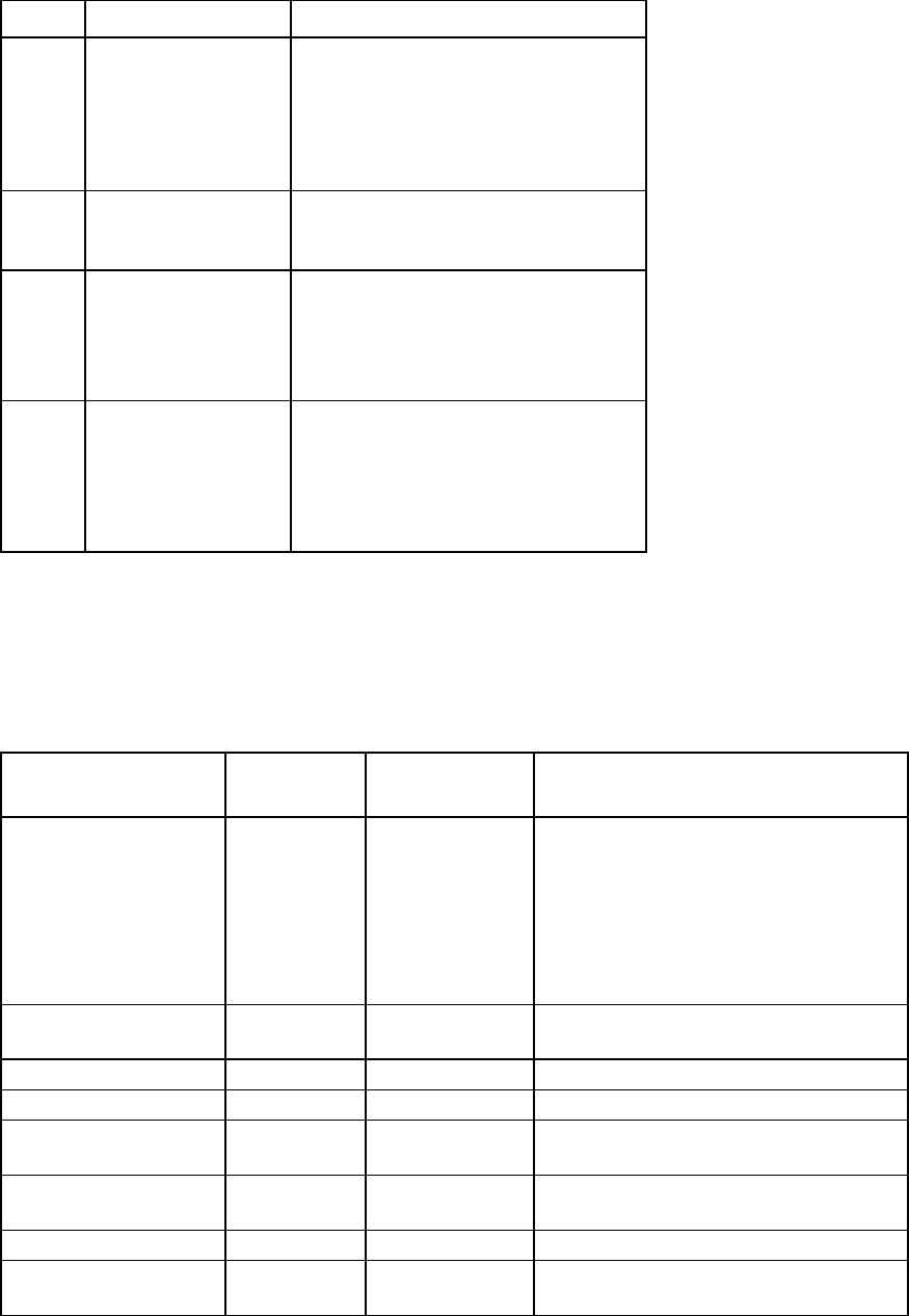
Systems Insight Display LED combinations
When the health LED on the front panel illuminates either amber or red, the server is experiencing a health
event. Combinations of illuminated Systems Insight Display LEDs, the system power LED, and the health LED
indicate system status.
Systems Insight Display
LED and color
Health LED System power
LED
Status
Processor (amber)
Red Amber One or more of the following conditions may
exist:
•
Processor in socket X has failed.
•
Processor X is not installed in the socket.
•
Processor X is unsupported.
•
ROM detects a failed processor during
POST
Processor (amber)
Amber
Green
Processor in socket X is in a pre-failure
condition.
DIMM (amber)
Red Green One or more DIMMs have failed.
DIMM (amber)
Amber Green DIMM in slot X is in a pre-failure condition.
Overtemperature (amber)
Amber Green The Health Driver has detected a cautionary
temperature level.
Overtemperature (amber)
Red Amber The server has detected a hardware critical
temperature level.
Fan (amber)
Amber Green One fan has failed or has been removed.
Fan (amber)
Red Green Two or more fans have failed or been
removed.