
Compaq ProLiant DL360 Ultra-Dense Server Deployment in Compaq Racks

Compaq ProLiant DL360 Ultra-Dense Server Deployment in Compaq Racks 71
128H-1100B-WWEN
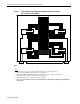
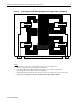
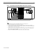
4.3.5.2 High Voltage 3-PDU Cabling Diagram (42U Rack)
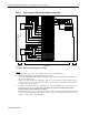
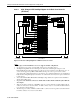
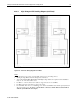
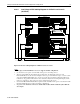
Figure 4-6. 42U rack cabling diagram for 3 PDUs.
Notes
• See Section 4.3.3 for power cord information and power cord routing choices.
• The high voltage PDUs shown in this figure are 24A rated.
• Two Vertical-Mount PDU Bracket Kits with High Voltage Cables are required for this installation.
All 22 cables will be used.
• There are Y-cables connected to each PDU to support 17 servers in the above figure. Eight of the Y-
cables are connected to 16 servers. The 9
th
Y-cable connects only to 1 server. The Y-cable end that is
not connected is shown with an *.
• For PDU-1 and PDU-2, there are 3 remaining power outlets, but the PDU rated current capacity has
been allocated for the servers. No power cords should be connected to all the unused outlets
marked with the symbol Ø in the above figure.
• For PDU-3, there are 8 power outlets still open. Only 11.2A of current capacity has been allocated for
the servers. If the remaining outlets (marked with **) are used, then the total current draw from these
should not exceed 12.8A for the 24A PDU.
PDU-2
PDU-1
PDU-3
<24A <24A
<24A
2 Lines (200-240V)
1 Line (200-240V)
22 Y Power Cords
*
*
*
40 1U Server
41 1U Server
42 1U Server
39 1U Server
37 1U Server
38 1U Server
36 1U Server
35 1U Server
34 1U Server
31 1U Server
33 1U Server
32 1U Server
30 1U Server
29 1U Server
28 1U Server
26 1U Server
27 1U Server
25 1U Server
24 1U Server
23 1U Server
22 1U Server
21 1U Server
20 1U Server
19 1U Server
17 1U Server
18 1U Server
16 1U Server
15 1U Server
14 1U Server
13 1U Server
12 1U Server
11 1U Server
10 1U Server
8 1U Server
9 1U Server
7 1U Server
6 1U Server
5 1U Server
4 1U Server
3 1U Server
2 1U Server
1 1U Server
10A
10A
10A
10A
10A
10A
10A
10A
PDU-2
10A
10A
10A
10A
*