
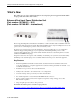
Compaq ProLiant DL360 Ultra-Dense Server Deployment in Compaq Racks

Compaq ProLiant DL360 Ultra-Dense Server Deployment in Compaq Racks 4
128H-1100B-WWEN
4.3 PDU Installation..................................................................................................................................66
4.3.1 Vertically Orienting the PDUs............................................................................66
4.3.2 Installing Multiple PDUs in a Rack.....................................................................67
4.3.2.1 Mounting 2 PDUs on One-Side.........................................................................67
4.3.2.2 Mounting 1 PDU on Each Side..........................................................................67
4.3.2.3 Mounting 3 PDUs.............................................................................................67
4.3.2.4 Mounting 4 PDUs.............................................................................................68
4.3.3 PDU Cord Set Choices.....................................................................................68
4.3.3.1 High Voltage Power Cords ...............................................................................68
4.3.3.2 Low Voltage Power Cords ................................................................................68
4.3.4 Power Cord Routing.........................................................................................69
4.3.5 PDU Cabling Diagrams ....................................................................................69
4.3.5.1 High Voltage 2-PDU Cabling Diagram (42U Rack).............................................70
4.3.5.2 High Voltage 3-PDU Cabling Diagram (42U Rack).............................................71
4.3.5.3 High Voltage 3-PDU Cabling Diagram for In-Rack Local Console (42U Rack).....72
04.3.5.4 High Voltage 4-PDU Cabling Diagram (42U Rack).............................................73
4.3.5.5 Low Voltage 4-PDU Cabling Diagram for In-Rack Local Console (42U Rack)......74
4.3.5.6 Low Voltage 4-PDU Cabling Diagram for Remote Console
(36 servers in a 42U Rack)...............................................................................75
4.3.5.7 Low Voltage 4-PDU Cabling Diagram for Remote Console
(42 servers in a 42U Rack)...............................................................................76
4.3.5.8 High Voltage 2-PDU Cabling Diagram with Y-Cables (36U Rack)........................77
4.3.5.9 High Voltage 3-PDU Cabling Diagram with Y-Cables (36U Rack)........................78
4.3.5.10 Low Voltage 4-PDU Cabling Diagram with Single Cables (36U Rack)..................79
4.3.5.11 High Voltage 2-PDU Cabling Diagram with Y-Cables (22U Rack)........................80
4.3.5.12 Low Voltage 2-PDU Cabling Diagram (18 servers in a 22U Rack).......................81
4.4 Rack Rails Installation.......................................................................................................................82
4.5 Server Installations in a Rack...........................................................................................................83
4.6 Cable Installation................................................................................................................................84
4.6.1 Power Cord Connection...................................................................................84
4.6.2 Console Management Choices .........................................................................85
4.6.2.1 Remote Console Management Cables ..............................................................85
4.6.2.2 Off-Rack Local Console Cabling.......................................................................85
4.6.2.3 In-Rack Local Console Cabling Using Server Console Switches .........................85
04.6.3 Cable Management Procedure.........................................................................88
4.6.3.1 Fixed-Rail Cable Management..........................................................................88
4.6.3.2 Sliding-Rail Cable Management........................................................................89
4.7 Completing the Installation ...............................................................................................................91
Appendix A -- Related Documents................................................................................92
Appendix B -- Parts Reference......................................................................................94