
Compaq ProLiant DL360 Ultra-Dense Server Deployment in Compaq Racks

Compaq ProLiant DL360 Ultra-Dense Server Deployment in Compaq Racks 18
128H-1100B-WWEN
2.2.1 Input Current and Thermal Dissipation Calculations
The input power is the key in deriving the input current and thermal dissipation. For a given input
power, the input current will vary depending on the input voltage level.
The relationship among the current, the voltage and the power for the power supply input is as
follows:
Input Current = Input Power / Input Voltage
For example,
Input Current = 100W /110V = 0.91A
Input Current = 100W /208V = 0.48A
The input power of a server depends on the operational state of the system. For example, during
the initial power up, a server consumes more power due to the hard disk drives spin-ups. It should
be noted that in ProLiant DL360, the two hard disk drives spin-up one after the other. Therefore,
the peak input power requirement changes significantly when the first drive is added, but not as
much when the second drive is added. After the power up, the input power varies depending on
the operating system and the application software running on the server. During standby, only the
auxiliary portion of the power supply is consuming power to support operations of a very limited
part of the system, for example, the Remote Insight Lights-Out Edition option, NICs, and so on.
The thermal dissipation can be calculated from the input power as follows:
Thermal Dissipation = Input Power * 3.41
For example,
Thermal Dissipation = 100W * 3.41 = 341 BTUs/hour
Thermal Dissipation = 292W * 3.41 = 996 BTUs/hour
The easiest way to calculate the thermal dissipation for the entire rack is to add the input power
requirements for all the servers and other units populated in a rack, and then multiply the total
input power by 3.41.
Section 2.2.3 explains more on how adding or removing of an optional subsystem component
affects the input power and thermal calculations.
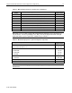
2.2.2 Measured Input Power
Table 2-3 lists the measured input power of ProLiant DL360 with varying subsystem
components, to illustrate the effects of adding or removing optional components. Table 2-4 lists
each subsystem component's input power derived from Table 2-3. A few test programs were run
to exercise various parts of the system, and the current and power were measured on the input
side of the power supply. The “peak” and “typical” input power values were measured during
power up and idle/normal operations, respectively.