
HP ProLiant DL360 G6 Server User Guide
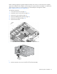
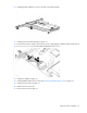
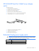
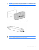
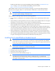
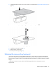
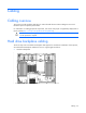
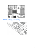
Table Of Contents
- HP ProLiant DL360 G6 Server User Guide
- Abstract
- Notice
- Contents
- Component identification
- Front panel components
- Front panel LEDs and buttons
- Rear panel LEDs and buttons
- System board components
- HP Systems Insight Display LEDs
- Systems Insight Display LED combinations
- SAS and SATA device numbers
- SAS and SATA hard drive LEDs
- SAS and SATA hard drive LED combinations
- Fan modules
- T-10/T-15 Torx screwdriver
- Operations
- Setup
- Hardware options installation
- Introduction
- Processor and fan module option
- Memory options
- Hot-plug SAS and SATA hard drive options
- DVD-ROM and DVD-RW drive option
- Hard drive blackplane option
- Controller options
- Expansion board options
- HP ProLiant DL360 G6 PCI thermal - power option
- HP NC522SFP Dual Port 10GbE Server Adapter option
- Redundant hot-plug power supply option
- HP Trusted Platform Module option
- Cabling
- Software and configuration utilities
- Troubleshooting
- System battery
- Regulatory compliance notices
- Regulatory compliance identification numbers
- Federal Communications Commission notice
- Declaration of conformity for products marked with the FCC logo, United States only
- Modifications
- Cables
- Canadian notice (Avis Canadien)
- European Union regulatory notice
- Disposal of waste equipment by users in private households in the European Union
- Japanese notice
- BSMI notice
- Korean notice
- Chinese notice
- Laser compliance
- Battery replacement notice
- Taiwan battery recycling notice
- Power cord statement for Japan
- Acoustics statement for Germany (Geräuschemission)
- Electrostatic discharge
- Specifications
- Technical support
- Acronyms and abbreviations
- Index
Hardware options installation 66
Enabling the TPM requires accessing the ROM-Based Setup Utility (RBSU) ("HP ROM-Based Setup
Utility" on page 73). For more information about RBSU, see the HP website
(http://www.hp.com/support/smartstart/documentation).
TPM installation requires the use of drive encryption technology, such as the Microsoft® Windows®
BitLocker™ Drive Encryption feature. For more information on BitLocker™, see the Microsoft website
(http://www.microsoft.com).
CAUTION: Always observe the guidelines in this document. Failure to follow these guidelines
can cause hardware damage or halt data access.
When installing or replacing a TPM, observe the following guidelines:
• Do not remove an installed TPM. Once installed, the TPM becomes a permanent part of the system
board.
• When installing or replacing hardware, HP service providers cannot enable the TPM or the encryption
technology. For security reasons, only the customer can enable these features.
• When returning a system board for service replacement, do not remove the TPM from the system board.
When requested, HP Service provides a TPM with the spare system board.
• Any attempt to remove an installed TPM from the system board breaks or disfigures the TPM security
rivet. Upon locating a broken or disfigured rivet on an installed TPM, administrators should consider the
system compromised and take appropriate measures to ensure the integrity of the system data.
• When using BitLocker™, always retain the recovery key/password. The recovery key/password is
required to enter Recovery Mode after BitLocker™ detects a possible compromise of system integrity.
• HP is not liable for blocked data access caused by improper TPM use. For operating instructions, see the
encryption technology feature documentation provided by the operating system.
Installing the Trusted Platform Module board
WARNING: To reduce the risk of personal injury, electric shock, or damage to the equipment,
remove the power cord to remove power from the server. The front panel Power On/Standby
button does not completely shut off system power. Portions of the power supply and some internal
circuitry remain active until AC power is removed.
WARNING: To reduce the risk of personal injury from hot surfaces, allow the drives and the
internal system components to cool before touching them.
1. Power down the server (on page 19).
2. Extend the server from the rack (on page 19).
3. Remove the access panel (on page 21).
4. Remove the PCI riser board assembly (on page 23).
CAUTION:
Any attempt to remove an installed TPM from the system board breaks or disfigures
the TPM security rivet. Upon locating a broken or disfigured rivet on an installed TPM,
administrators should consider the system compromised and take appropriate measures to ensure
the integrity of the system data.