
HP ProLiant DL360 G6 Server User Guide
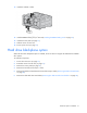
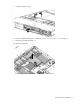

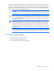


Table Of Contents
- HP ProLiant DL360 G6 Server User Guide
- Abstract
- Notice
- Contents
- Component identification
- Front panel components
- Front panel LEDs and buttons
- Rear panel LEDs and buttons
- System board components
- HP Systems Insight Display LEDs
- Systems Insight Display LED combinations
- SAS and SATA device numbers
- SAS and SATA hard drive LEDs
- SAS and SATA hard drive LED combinations
- Fan modules
- T-10/T-15 Torx screwdriver
- Operations
- Setup
- Hardware options installation
- Introduction
- Processor and fan module option
- Memory options
- Hot-plug SAS and SATA hard drive options
- DVD-ROM and DVD-RW drive option
- Hard drive blackplane option
- Controller options
- Expansion board options
- HP ProLiant DL360 G6 PCI thermal - power option
- HP NC522SFP Dual Port 10GbE Server Adapter option
- Redundant hot-plug power supply option
- HP Trusted Platform Module option
- Cabling
- Software and configuration utilities
- Troubleshooting
- System battery
- Regulatory compliance notices
- Regulatory compliance identification numbers
- Federal Communications Commission notice
- Declaration of conformity for products marked with the FCC logo, United States only
- Modifications
- Cables
- Canadian notice (Avis Canadien)
- European Union regulatory notice
- Disposal of waste equipment by users in private households in the European Union
- Japanese notice
- BSMI notice
- Korean notice
- Chinese notice
- Laser compliance
- Battery replacement notice
- Taiwan battery recycling notice
- Power cord statement for Japan
- Acoustics statement for Germany (Geräuschemission)
- Electrostatic discharge
- Specifications
- Technical support
- Acronyms and abbreviations
- Index
Hardware options installation 56
The Battery-Backed Write Cache Enabler, also called the battery pack, works with the cache module to
provide transportable data protection, increase overall controller performance, and maintain any cached
data for up to 72 hours. The NiMH batteries in the battery pack are continuously recharged through a
trickle-charging process whenever the system power is on. Under normal operating conditions, the battery
pack lasts for 3 years before replacement is necessary.
CAUTION: To prevent a server malfunction or damage to the equipment, do not add or remove
the battery pack while an array capacity expansion, RAID level migration, or stripe size migration
is in progress.
CAUTION: After the server is powered down, wait 15 seconds and then check the amber LED
before unplugging the cable from the cache module. If the amber LED blinks after 15 seconds, do
not remove the cable from the cache module. The cache module is backing up data, and data is
lost if the cable is detached.
IMPORTANT: The battery pack might have a low charge when installed. In this case, a POST
error message is displayed when the server is powered up, indicating that the battery pack is
temporarily disabled. No action is necessary on your part. The internal circuitry automatically
recharges the batteries and enables the battery pack. This process might take up to four hours.
During this time, the cache module functions properly, but without the performance advantage of
the battery pack.
NOTE: The data protection and the time limit also apply if a power outage occurs. When power
is restored to the system, an initialization process writes the preserved data to the hard drives.
Installing the cache module
1. Power down the server (on page 19).
2. Extend the server from the rack (on page 19).
3. Remove the access panel (on page 21).
4. Remove the PCI riser board assembly (on page 23).