
HP ProLiant DL360 G6 Server User Guide
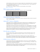
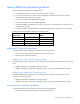
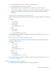
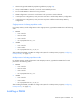
Table Of Contents
- HP ProLiant DL360 G6 Server User Guide
- Abstract
- Notice
- Contents
- Component identification
- Front panel components
- Front panel LEDs and buttons
- Rear panel LEDs and buttons
- System board components
- HP Systems Insight Display LEDs
- Systems Insight Display LED combinations
- SAS and SATA device numbers
- SAS and SATA hard drive LEDs
- SAS and SATA hard drive LED combinations
- Fan modules
- T-10/T-15 Torx screwdriver
- Operations
- Setup
- Hardware options installation
- Introduction
- Processor and fan module option
- Memory options
- Hot-plug SAS and SATA hard drive options
- DVD-ROM and DVD-RW drive option
- Hard drive blackplane option
- Controller options
- Expansion board options
- HP ProLiant DL360 G6 PCI thermal - power option
- HP NC522SFP Dual Port 10GbE Server Adapter option
- Redundant hot-plug power supply option
- HP Trusted Platform Module option
- Cabling
- Software and configuration utilities
- Troubleshooting
- System battery
- Regulatory compliance notices
- Regulatory compliance identification numbers
- Federal Communications Commission notice
- Declaration of conformity for products marked with the FCC logo, United States only
- Modifications
- Cables
- Canadian notice (Avis Canadien)
- European Union regulatory notice
- Disposal of waste equipment by users in private households in the European Union
- Japanese notice
- BSMI notice
- Korean notice
- Chinese notice
- Laser compliance
- Battery replacement notice
- Taiwan battery recycling notice
- Power cord statement for Japan
- Acoustics statement for Germany (Geräuschemission)
- Electrostatic discharge
- Specifications
- Technical support
- Acronyms and abbreviations
- Index
Hardware options installation 43
• Always install DIMMs in channels 1 and 2 for each installed processor.
• Do not install DIMMs in channel 3 for any processor.
• DIMMs installed on channel 1 and channel 2 of an installed processor must be identical.
• In multi-processor configurations, each processor must have a valid Mirrored Memory configuration.
• In multi-processor configurations, each processor may have a different valid Mirrored Memory
configuration.
Single-processor Mirrored Memory population order
For Mirrored Memory mode configurations with a single processor, populate the DIMM slots in the following
order:
• RDIMM
o First: A and B
o Next: D and E
o Last: G and H
o Do not populate slots C, F, or I.
• UDIMM
o First: A and B
o Last: D and E
o Do not populate slots C, F, G, H, or I.
After installing the DIMMs, use RBSU to configure the system for Mirrored Memory support ("Configuring
mirrored memory" on page 76).
Multi-processor Mirrored Memory population order
For Mirrored Memory mode configurations with multiple processors, populate the DIMM slots for each
processor in the following order:
• RDIMM
o First: A and B
o Next: D and E
o Last: G and H
o Do not populate slots C, F, or I.
• UDIMM
o First: A and B
o Last: D and E
o Do not populate slots C, F, G, H, or I.
After installing the DIMMs, use RBSU to configure the system for mirrored memory support ("Configuring
mirrored memory" on page 76).
Lockstep Memory population guidelines
For Lockstep memory mode configurations, observe the following guidelines: