
HP ProLiant DL360 G6 Server User Guide
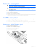
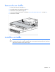
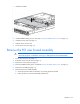
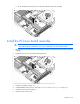
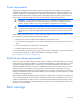
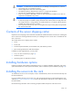
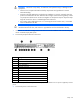
Table Of Contents
- HP ProLiant DL360 G6 Server User Guide
- Abstract
- Notice
- Contents
- Component identification
- Front panel components
- Front panel LEDs and buttons
- Rear panel LEDs and buttons
- System board components
- HP Systems Insight Display LEDs
- Systems Insight Display LED combinations
- SAS and SATA device numbers
- SAS and SATA hard drive LEDs
- SAS and SATA hard drive LED combinations
- Fan modules
- T-10/T-15 Torx screwdriver
- Operations
- Setup
- Hardware options installation
- Introduction
- Processor and fan module option
- Memory options
- Hot-plug SAS and SATA hard drive options
- DVD-ROM and DVD-RW drive option
- Hard drive blackplane option
- Controller options
- Expansion board options
- HP ProLiant DL360 G6 PCI thermal - power option
- HP NC522SFP Dual Port 10GbE Server Adapter option
- Redundant hot-plug power supply option
- HP Trusted Platform Module option
- Cabling
- Software and configuration utilities
- Troubleshooting
- System battery
- Regulatory compliance notices
- Regulatory compliance identification numbers
- Federal Communications Commission notice
- Declaration of conformity for products marked with the FCC logo, United States only
- Modifications
- Cables
- Canadian notice (Avis Canadien)
- European Union regulatory notice
- Disposal of waste equipment by users in private households in the European Union
- Japanese notice
- BSMI notice
- Korean notice
- Chinese notice
- Laser compliance
- Battery replacement notice
- Taiwan battery recycling notice
- Power cord statement for Japan
- Acoustics statement for Germany (Geräuschemission)
- Electrostatic discharge
- Specifications
- Technical support
- Acronyms and abbreviations
- Index
Operations 21
Remove the access panel
WARNING: To reduce the risk of personal injury from hot surfaces, allow the drives and the
internal system components to cool before touching them.
CAUTION: Do not operate the server for long periods with the access panel open or removed.
Operating the server in this manner results in improper airflow and improper cooling that can
lead to thermal damage.
To remove the component:
1. Power down the server (on page 19).
2. Extend the server from the rack (on page 19).
3. Open the locking latch, slide the access panel to the rear of the chassis, and remove the access panel.
If the locking latch is locked use a T-15 Torx screwdriver to unlock the latch.
Install the access panel
1. Place the access panel on top of the server with the hood latch open. Allow the panel to extend past the
rear of the server approximately 1.25 cm (0.5 in).
2. Push down on the hood latch. The access panel slides to a closed position.
3. Use the T-15 Torx screwdriver provided with the server to tighten the security screw on the hood latch.
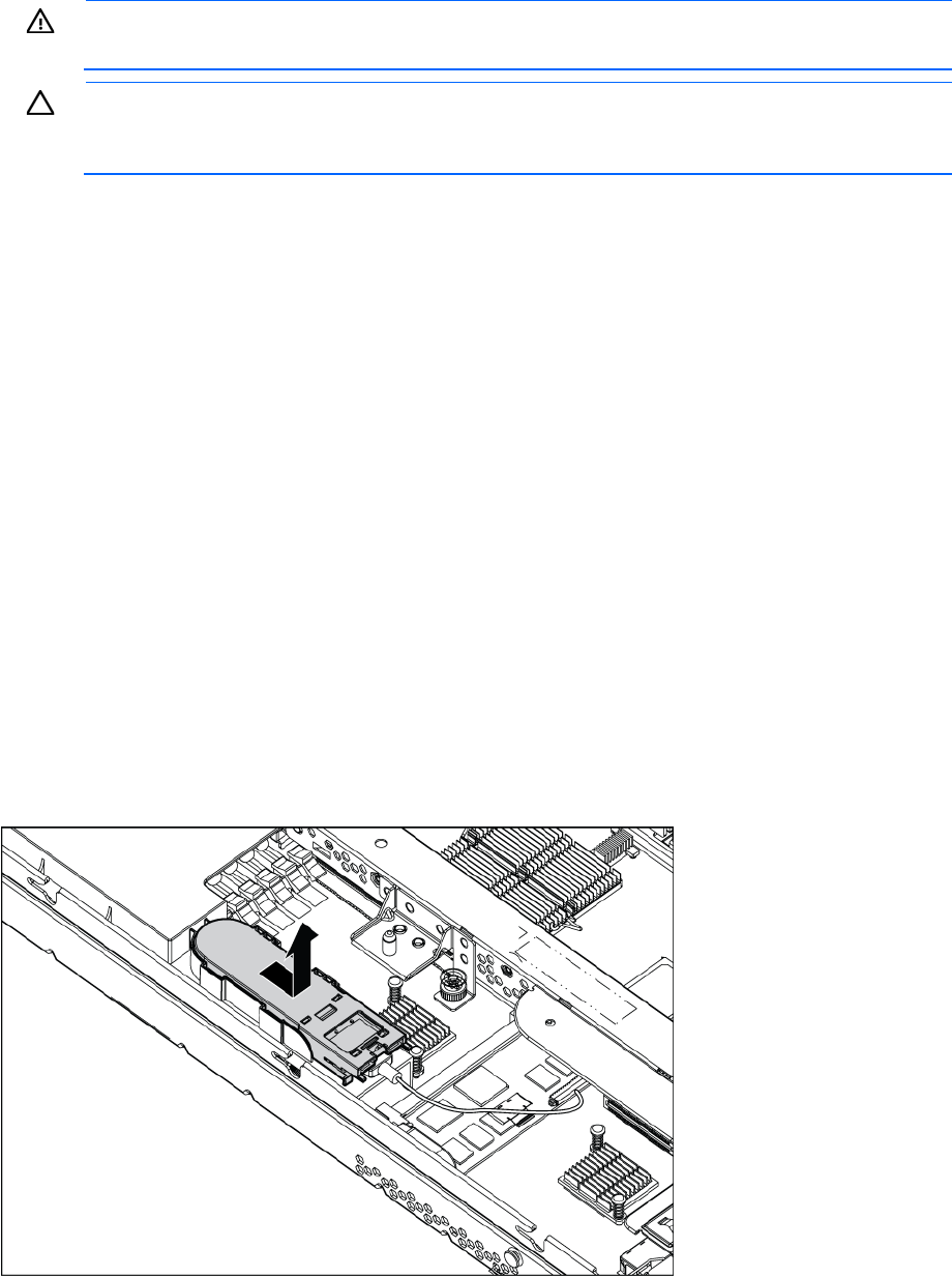
Remove the BBWC battery pack
1. Power down the server (on page 19).
2. Extend the server from the rack (on page 19).
3. Remove the access panel (on page 21).
4. Remove the BBWC battery pack.