
HP ProLiant DL360 G6 Server User Guide
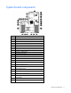
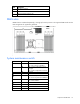
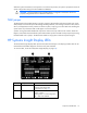
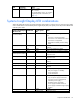
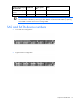
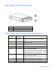
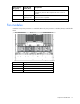
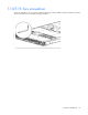
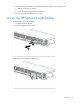
Table Of Contents
- HP ProLiant DL360 G6 Server User Guide
- Abstract
- Notice
- Contents
- Component identification
- Front panel components
- Front panel LEDs and buttons
- Rear panel LEDs and buttons
- System board components
- HP Systems Insight Display LEDs
- Systems Insight Display LED combinations
- SAS and SATA device numbers
- SAS and SATA hard drive LEDs
- SAS and SATA hard drive LED combinations
- Fan modules
- T-10/T-15 Torx screwdriver
- Operations
- Setup
- Hardware options installation
- Introduction
- Processor and fan module option
- Memory options
- Hot-plug SAS and SATA hard drive options
- DVD-ROM and DVD-RW drive option
- Hard drive blackplane option
- Controller options
- Expansion board options
- HP ProLiant DL360 G6 PCI thermal - power option
- HP NC522SFP Dual Port 10GbE Server Adapter option
- Redundant hot-plug power supply option
- HP Trusted Platform Module option
- Cabling
- Software and configuration utilities
- Troubleshooting
- System battery
- Regulatory compliance notices
- Regulatory compliance identification numbers
- Federal Communications Commission notice
- Declaration of conformity for products marked with the FCC logo, United States only
- Modifications
- Cables
- Canadian notice (Avis Canadien)
- European Union regulatory notice
- Disposal of waste equipment by users in private households in the European Union
- Japanese notice
- BSMI notice
- Korean notice
- Chinese notice
- Laser compliance
- Battery replacement notice
- Taiwan battery recycling notice
- Power cord statement for Japan
- Acoustics statement for Germany (Geräuschemission)
- Electrostatic discharge
- Specifications
- Technical support
- Acronyms and abbreviations
- Index
Component identification 12
Item Description
24
PCI power connector
25
TPM connector
26
PCIe riser board connectors (2)
DIMM slots
DIMM slots are numbered sequentially (1 through 9) for each processor. The supported AMP modes use the
letter assignments for population guidelines.
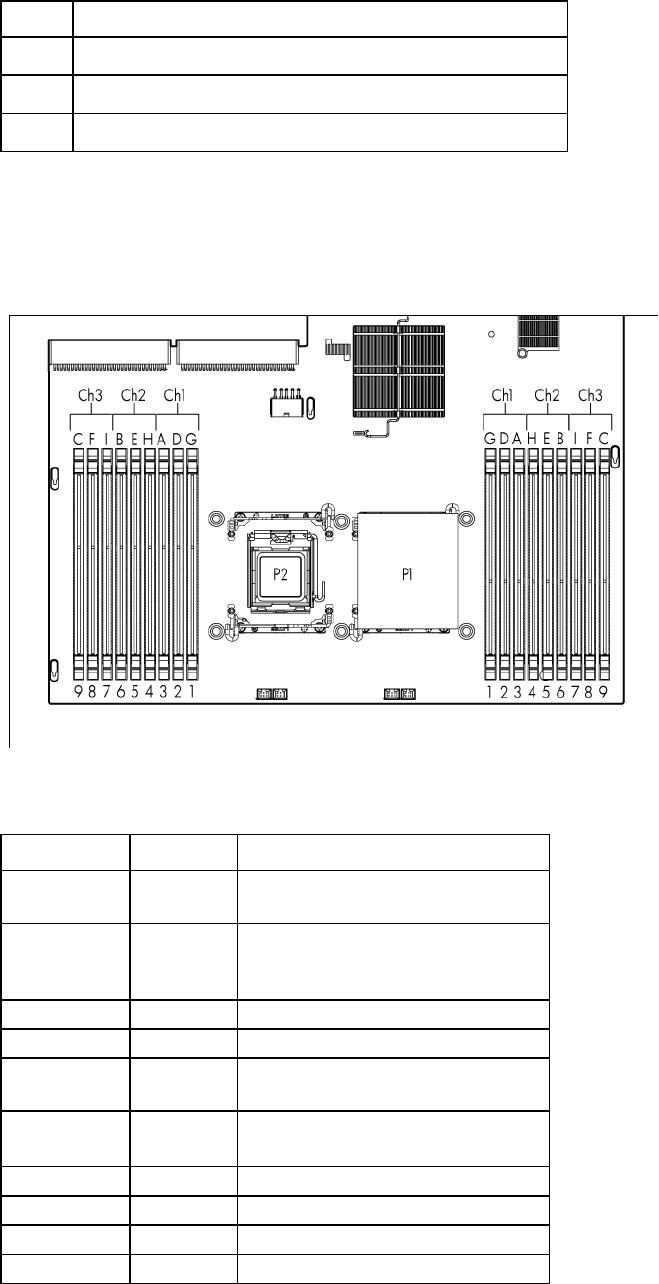
System maintenance switch
Position Default Function
S1
Off Off = iLO 2 security is enabled.
On = iLO 2 security is disabled.
S2
Off Off = System configuration can be
changed.
On = System configuration is locked.
S3
Off Reserved
S4
Off Reserved
S5
Off Off = Power-on password is enabled.
On = Power-on password is disabled.
S6
Off Off = No function
On = Clear NVRAM
S7
— Reserved
S8
— Reserved
S9
— Reserved
S10
— Reserved