
HP ProLiant DL360 G6 Server User Guide
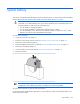
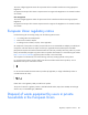
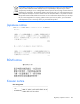
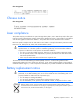
Table Of Contents
- HP ProLiant DL360 G6 Server User Guide
- Abstract
- Notice
- Contents
- Component identification
- Front panel components
- Front panel LEDs and buttons
- Rear panel LEDs and buttons
- System board components
- HP Systems Insight Display LEDs
- Systems Insight Display LED combinations
- SAS and SATA device numbers
- SAS and SATA hard drive LEDs
- SAS and SATA hard drive LED combinations
- Fan modules
- T-10/T-15 Torx screwdriver
- Operations
- Setup
- Hardware options installation
- Introduction
- Processor and fan module option
- Memory options
- Hot-plug SAS and SATA hard drive options
- DVD-ROM and DVD-RW drive option
- Hard drive blackplane option
- Controller options
- Expansion board options
- HP ProLiant DL360 G6 PCI thermal - power option
- HP NC522SFP Dual Port 10GbE Server Adapter option
- Redundant hot-plug power supply option
- HP Trusted Platform Module option
- Cabling
- Software and configuration utilities
- Troubleshooting
- System battery
- Regulatory compliance notices
- Regulatory compliance identification numbers
- Federal Communications Commission notice
- Declaration of conformity for products marked with the FCC logo, United States only
- Modifications
- Cables
- Canadian notice (Avis Canadien)
- European Union regulatory notice
- Disposal of waste equipment by users in private households in the European Union
- Japanese notice
- BSMI notice
- Korean notice
- Chinese notice
- Laser compliance
- Battery replacement notice
- Taiwan battery recycling notice
- Power cord statement for Japan
- Acoustics statement for Germany (Geräuschemission)
- Electrostatic discharge
- Specifications
- Technical support
- Acronyms and abbreviations
- Index
System battery 102
System battery
If the server no longer automatically displays the correct date and time, you may need to replace the battery
that provides power to the real-time clock. Under normal use, battery life is 5 to 10 years.
WARNING: The computer contains an internal lithium manganese dioxide, a vanadium
pentoxide, or an alkaline battery pack. A risk of fire and burns exists if the battery pack is not
properly handled. To reduce the risk of personal injury:
• Do not attempt to recharge the battery.
• Do not expose the battery to temperatures higher than 60°C (140°F).
• Do not disassemble, crush, puncture, short external contacts, or dispose of in fire or water.
• Replace only with the spare designated for this product.
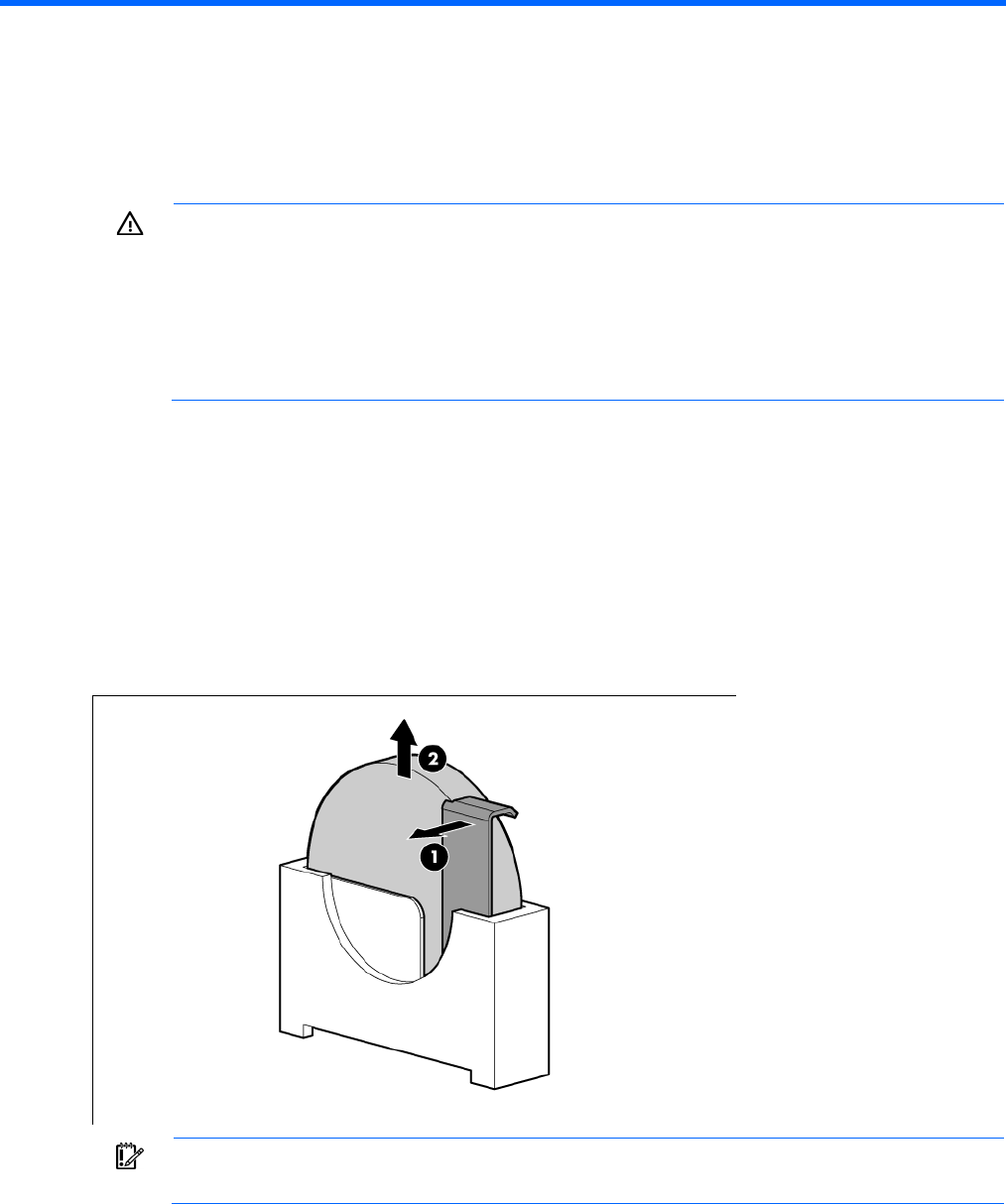
To remove the component:
1. Power down the server (on page 19).
2. Extend or remove the server from the rack ("Extend the server from the rack" on page 19).
3. Remove the access panel (on page 21).
4. Remove the BBWC battery pack, if installed ("Remove the BBWC battery pack" on page 21).
5. Remove the air baffle (on page 22).
6. Locate the battery on the system board ("System board components" on page 11).
7. Remove the battery.
IMPORTANT: Replacing the system board battery resets the system ROM to its default
configuration. After replacing the battery, reconfigure the system through RBSU.
To replace the component, reverse the removal procedure.
For more information about battery replacement or proper disposal, contact an authorized reseller or an
authorized service provider.