
HP ProLiant DL360 G6 Server MSG

Removal and replacement procedures 52
3.
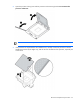
Remove the access panel ("Access panel" on page 26).
4. Remove all hard drives ("SAS and SATA hard drive" on page 28).
5. Remove all power supplies ("Server warnings and cautions" on page 25).
6. Remove the BBWC battery pack, if installed ("BBWC battery pack" on page 35).
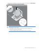
7. Remove the air baffle ("Air baffle" on page 36).
CAUTION: To prevent damage to the server or expansion boards, power down the server and
remove all AC power cords before removing or installing the PCI riser board assembly.
8. Remove the PCI riser board assembly ("PCI riser board assembly" on page 36).
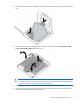
9. Remove all fan modules ("Fan module" on page 33).
10. Remove the fan blank ("Fan blank" on page 34).
11. Disconnect all cables connected to the system board ("System board components" on page 67). For
more information, see "Cabling (on page 77)."
12. Remove the cache module ("Cache module" on page 39).
13. Remove the optional hard drive backplane ("Optional hard drive backplane assembly (top)" on page
40).
14. Remove the hard drive backplane ("Standard hard drive backplane assembly (bottom)" on page 40).
15. Remove all DIMMs ("DIMMs" on page 42).
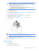
16. Remove the heatsink ("Heatsink" on page 43).
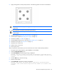
17. Open the processor locking lever and the processor socket retaining bracket.
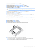
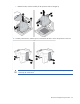
18. Using the processor tool, remove the processor from the system board:
a. Line up the processor tool, ensuring the locking lever graphic on the tool is oriented correctly.
b. Press in on the plastic tabs, and then place the tool on the processor.