
ProLiant DL360 Generation 4p Server (SAS Model) Maintenance and Service Guide

Server component identification 38
Server component identification
In this section
Front panel LEDs and buttons................................................................................................................... 38
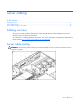
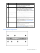
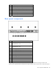
Front panel components .......................................................................................................................... 39
Rear panel components........................................................................................................................... 40
Rear panel LEDs and buttons ................................................................................................................... 41
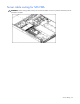
System board components....................................................................................................................... 42
System board LEDs................................................................................................................................. 43
System LEDs and internal health LED combinations ..................................................................................... 44
Internal USB connector............................................................................................................................ 46
SAS and SATA device numbers ............................................................................................................... 46
Identifying the status of a hard drive......................................................................................................... 47
SAS and SATA hard drive LED combinations............................................................................................. 47
Fan module locations.............................................................................................................................. 48
Processor zone fan module LED ............................................................................................................... 49
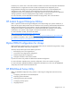
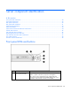
Front panel LEDs and buttons
Item Description Status
1
Power On/Standby button
and system power LED
Green = System is on.
Amber = System is shut down, but power is still applied.
Off = Power cord is not attached, power supply failure has
occurred, no power supplies are installed, facility power is not
available, or the DC-to-DC converter is not installed.