
ProLiant DL360 Generation 4p Server (SAS Model) Maintenance and Service Guide

Removal and replacement procedures 21
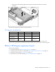
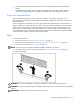
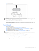
c.
Lift the front of the assembly slightly and unseat the riser boards from the PCI riser board
connectors.
To replace the component, reverse the removal procedure.
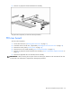
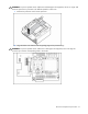
PCI expansion slot definitions
Slot* Board Size Connector Interconnect
PCI-X expansion slot 1 Half-length 133 MHz, 3.3 V 64-bit
PCI-X expansion slot 2 Full-length 133 MHz, 3.3 V 64-bit
PCI Express expansion
slot 1 (optional)
Half-length x8 x1, x4, or x8
PCI Express expansion
slot 2 (optional)
Full-length x8 x1, x4, or x8
* Depending on the model of the server, slot 1 or slot 2 will be pre-populated with a storage controller. If the
expansion slot is populated with the standard PCI-X storage controller card, it should not be converted to PCI Express.
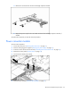
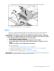
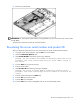
PCI-X or PCI Express expansion board
To remove the component:
1. Power down the server ("Powering down the server" on page 11).
2. Extend the server from the rack, if applicable ("Extending the server from the rack" on page 12).
3. Remove the access panel ("Access panel" on page 14).
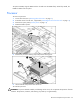
4. Remove the PCI riser board assembly ("PCI riser board assembly" on page 20).