
ProLiant DL360 Generation 4p Server (SAS Model) Maintenance and Service Guide

Removal and replacement procedures 20
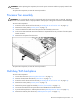
9.
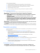
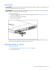
Remove the multi-bay release latch screw with a T-15 Torx screwdriver.
10. Remove the multi-bay release latch.
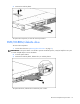
11. Remove the two screws that fasten the multi-bay/SAS backplane to the chassis.
12. Remove the component from the server.
To replace the component, reverse the removal procedure.
PCI riser board assembly
CAUTION: To prevent damage to the server or expansion boards, power down the server and remove all
AC power cords before removing or installing the expansion boards.
IMPORTANT: Be sure that all DIMM slot latches are closed to provide adequate clearance before
removing the PCI riser board assembly with a half-length expansion board.
To remove the component:
1. Power down the server ("Powering down the server" on page 11).
2. Extend the server from the rack, if applicable ("Extending the server from the rack" on page 12).
3. Remove the access panel ("Access panel" on page 14).
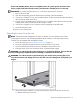
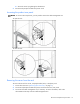
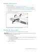
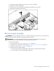
4. Remove the PCI riser board assembly:
a. Disconnect any internal or external cables connected to any existing expansion boards.
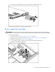
b. Loosen the four PCI riser board assembly thumbscrews.